


26
ORI-46.650 Jupiter Magnetostrictive Transmitters
ORI-46.650 Jupiter Magnetostrictive Transmitters
27
1 PV
2 PV Analog Output
3 PV % Output
4 Device Setup
5 Setup Wizard
6 Diagnostics
7 Measured Values
1 Present Status
2 Event History
3 Advanced Diagnostics
4 Echo Curves
5 Echo History
6 Trend Data
1 Level Ticks
2 Echo Strength
3 Ifc Ticks
4 Ifc Echo Strength
5 Lvl Noise/Threshold
6 Lvl Noise Location
7 Ifc Noise/Threshold
8 Ifc Noise Location
9 Distance
10 Fdbk Current
1 Event Log
2 Refresh History
3 Reset History
4 Set Clock
1 Present Temperature
2 Max Temperature
3 Min Temperature
4 Reset Max/Min Temp
1 Internal Values
2 Elec Temperatures
3 Transmitter Tests
1 Echo Graph
2 Curve 1
3 Curve 2
4 Refresh Graph
5 Zoom
6 Echo History Log
7 Refresh History
8 History Setup
9 Delete History
10 Set Clock
1 Enter Password
2 Sensitivity
3 Blocking Distance
4 Upr Lvl Polarity
5 Ifc Lvl Polarity
6 Lvl Thresh Mode
7 Lvl Thresh Value
8 Ifc Lvl Thresh Mode
9 Ifc Lvl Thresh Value
1 Echo Graph
2 Curve 1
3 Curve 2
4 Refresh Graph
5 Zoom
6 Save Ref Echo Curve
7 Parameters
1 Trend Data
2 Level
3 Ifc Level
4 Upr Thickness
5 Echo Strength
6 Ifc Echo Strength
7 Analog Output
8 % Output
9 Data Log Setup
1 Echo History Mode
2 Event Triggers
3 Time Triggers
4 Set Clock
5 Enter Password
1 Trending Variables
2 Time Setup
3 Set Clock
4 Enter Password
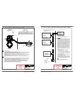
1.6.4 HART Menu – Model JM4
NOTE: Numbered menu boxes below correspond to numbered tables on Section 1.6.5.
15
16
17
18
19
20
21
22
23
24
25
1.6.5 HART Menu Items
1
Display
Description
1
PV
Digital representation that tracks the Analog Output Number 1, under normal operating modes.
Level of material on the probe.
(When in interface mode, this value corresponds to the level of the upper surface.)
2
PV Analog Output
Digital representation that tracks the Analog Output Number 1, under normal operating modes.
Analog Output Value: Value that tracks the Digital Value representation, under normal operating
modes
3
PV % Output
Digital representation that tracks the Analog Output Number 1, under normal operating modes.
Analog Output Value: Value that tracks the Digital Value representation, under normal operating
modes
4
Device Setup
Set of menus to allow full configuration of the transmitter.
5
Setup Wizard
6
Diagnostics
Menu showing Diagnostic information.
7
Measured Values
A read-only screen that presents the various output values that can be displayed.
(Available options will depend on Measurement Type.)
2
Display
Description
1
Identity
A read-only screen that displays basic manufacturer’s information about the transmitter.
2
Basic Config
A menu that allows for basic configuration of the transmitter.
3
Volume Config
A menu that allows for entry of known tank shapes or custom tables for volumetric output. This
menu contains various tank shapes for easy configuration for those applications requiring Volu
-
metric output.
4
I/O Config
Allows for configuration of the 4/20mA Analog Output, which includes the lower and upper set
points, Damping, and Failure Alarms.
5
Local Display
Config
Allows for customized presentation of information on the graphic LCD. The LCD can be con-
figured to display up to two Measured Variables, along with a Tag, Bar Graph, and NE 107
symbols.
6
Advanced Config
Allows for more advanced configuration and troubleshooting.
(Advanced Password may be required for access to parameters.)
Contact Technical Support.
7
Factory Config
Allows viewing of Factory Parameters.
These parameters are protected by a factory password and are not intended to be adjusted in
the field.
* For ‘Volume & Level’ Measurement Type only.