


40
ORI-46.650 Jupiter Magnetostrictive Transmitters
ORI-46.650 Jupiter Magnetostrictive Transmitters
41
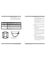
2.3.2 Troubleshooting Table
Problem
Solution
Blank display
Ensure local Keypad / LCD is properly installed.
Remove power and reapply power to the unit.
Check to see if LED on module is illuminated.
Check voltage at terminal board.
If jumper is in place under display, remove jumper.
Transmitter does not track level (External Mount)
(Direct Insertion)
Check echo curve for noise preventing tracking of level.
Remove transmitter and probe from piping column and
test with re-alignment magnet. Run magnet from bottom
to top of probe.
Check zero and span calibration. If no change in output,
consult the factory.
Float inside the level gauge is moving slowly or not at all.
Ensure that the magnetic level indicator is plumb.
The process fluid being measured may be too viscous
and heat tracing may be required to make the material
more fluid.
The specific gravity of the process fluid and float weight
may need to be reverified.
The liquid being measured may contain magnetic
particles collecting on the magnetic section of the float
causing drag. If this happens magnetic trap assemblies
can be purchased from the factory.
Visual inspection of the float may be required to see if
the float has collapsed.
LEVEL, % OUTPUT, and LOOP values are all
inaccurate.
Wipe probe with external magnet.
Confirm configuration settings.
Consult factory.
LEVEL, % OUTPUT, and LOOP values fluctuate.
Check echo curve for noise levels that could be affecting
level reading.
Turbulence, increase damping factor until readings
stabilize.
Level reading on display is correct, but loop value is
stuck at 4 mA.
Set poll address to zero.
As mentioned above, the indicators can be assignable (via the
a DTM or host system) by the user to any (or none) of the
NAMUR recommended Status Signal categories: Failure, Func-
tion Check, Out of Specification, and Maintenance Required.
The FOUNDATION fieldbus transmitter version of the Model
JM4 was implemented according to the Field Diagnostics Pro-
file, which is consistent with the objectives of NE 107.
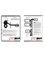
In the FOUNDATION fieldbus version, diagnostic indicators
can be mapped to multiple categories, an example is shown in
the diagram at left.
In the FOUNDATION fieldbus version, diagnostic indicators
can be mapped to multiple categories, an example is shown in
the diagram at left.
In this example, “Calibration Required” is mapped to both the
Out of Specification and Maintenance Required status signals,
and the diagnostic indicator named “High Temperature” is
mapped to none of the signals.
Indicators that are mapped to the Failure category will normally
result in a current loop alarm output. The alarm state for HART
transmitters is configurable as high (22 mA), Low (3.6 mA), or
Hold (last value).
Users will not have the ability to unassign certain indicators
from the Failure signal category as the Model JM4 user interfac-
es will prohibit or reject such re-assignment entries). This is to
ensure that current loop alarms are asserted in situations where
the device is not able to provide measurements due to critical
failures. (For example, if the alarm selection has not been set to
Hold, or a fixed current mode is in effect.)
A default mapping of all diagnostic indicators will be applied
initially, and can be re-applied through use of a reset function.
Refer to the table below for a complete listing of the Model JM4
diagnostic indicators, along with their explanations, default cate-
gories, and recommended remedies.
NOTES: 1) The remedies shown in this table can also be seen on the
transmitter LCD by viewing the present status screen when
the device is in a diagnostic condition.
2) Those indicators showing failure as the default result in an
alarm condition.
Analog Output Error
Failure
Function
Check
Out of
Specification
Maintenance
Required
Diagnostic Indicators
Calibration
Required
High
Temperature
Echo Lost
Dry
Probe
Fig. 2-2. Namur NE 107 Status Signals - Venn
Diagram