Magnescale LY71 Скачать руководство пользователя страница 17

LY71

 (J) 

2-9

2. 応用操作

2-15-5. 表示モードを外部に取出す

結線が必要です。

カウント表示Cは参考表示のため、出力保存の対象外です。

設置マニュアル「4-3. 詳細設定をする」(汎用入力)

2-15-6. 基準位置の再現を外部信号で行なう

「2-3-2. 基準位置の再現」の操作を、外部信号で行なうことができます。
結線が必要です。

Ex. IN A

: カウンタ表示A用の入力信号

Ex. IN B

: カウンタ表示B用の入力信号

Ex. IN C

: 使用不可

設置マニュアル「4-3. 詳細設定をする」(汎用入力)

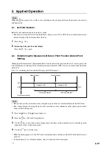
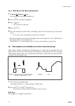
2-15-7. 原点通過信号を外部に取出す

原点操作時、原点を通過したときに原点通過信号を取出すことができます。原点操作をしていな
いときに原点通過しても、信号は出力されません。
結線が必要です。

OUT A1, OUT A2

: カウンタ表示Aの出力

OUT B1, OUT B2

: カウンタ表示Bの出力

カウント表示Cは参考表示のため、出力保存の対象外です。

設置マニュアル「4-3. 詳細設定をする」(汎用出力)

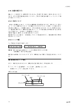
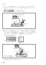
2-15-8. ホールド機能を外部から操作する

ホールド機能 (ラッチ、ポーズ) を外部信号で行なうことができます。1度ON / OFFすると働き、
もう1度ON / OFFすると解除されます。
結線が必要です。

Ex. IN A

: カウンタ表示A用の入力信号

Ex. IN B

: カウンタ表示B用の入力信号

Ex. IN C

: カウンタ表示C用の入力信号

設置マニュアル「4-3. 詳細設定をする」(汎用入力)

Содержание LY71

Страница 1: ...LY71 Instruction Manual Operating manual Counter Unit Read all the instructions in the manual carefully before use and strictly follow them Keep the manual for future references...

Страница 2: ...LY71...

Страница 3: ...3 1 2 2 2 3 2 2 3 2 4 2 3 2 5 2 4 2 6 2 4 2 7 2 4 2 8 2 4 2 9 2 5 2 10 2 5 2 11 2 2 5 2 12 2 6 2 13 2 6 2 14 2 7 2 15 2 8 2 15 1 2 8 2 15 2 2 8 2 15 3 2 8 2 15 4 2 8 2 15 5 2 9 2 15 6 2 9 2 15 7 2 9...

Страница 4: ...ii J LY71...

Страница 5: ...LY71 J 1 1 1 4 4 2 1 1 4 1 1 4 1 2 A 3 2 16 1 2 1 2 15 2 C 1 3 1 2 3 ABS 4 5 4 1 1 0 005...

Страница 6: ...1 2 J LY71 1 4 1 A 2 3 B 2 MAX C 2 MIN 1 5 1 2 1 4 1 7 2 15 9 1...

Страница 7: ...LY71 J 1 3 1 6 P P 1 B ABS 2 2 3 ABS B P P P P P P MAX MIN 2 15 3 4 3 1 7 1 A ABS 2 3 P P 2 15 10 C 4 1...

Страница 8: ...1 4 J LY71...

Страница 9: ...LY71 J 2 1 2 2 1 INC ABS 2 2 ABS INC P P INC P P 1 2 ABS 3 4 INC ABS C ABS ABS INC INC INC...

Страница 10: ...2 2 J LY71 2 2 ABS INC ABS INC ABS ABS INC ABS P P INC ABS 2 1 1 2 2 3 OFF 4 3 2 3 1 1 2 ABS 3 4 5 6 2 INC ABS...

Страница 11: ...LY71 J 2 3 2 3 2 7 REF 8 ABS 9 10 11 2 15 6 C 2 4 1 4 3 2 2 1 q w 2 q w...

Страница 12: ...2 4 J LY71 2 2 5 1 4 3 2 2 6 4 3 2 7 4 3 2 8 4 3 4 3 9...

Страница 13: ...LY71 J 2 5 2 2 9 4 3 ON 2 10 4 3 2 11 2 2 2 4 2 2 2 2 12...

Страница 14: ...2 6 J LY71 2 2 12 2 ABS INC 1 1 A 2 A 3 B B A A B B A 1 B 1 2 13 1 B 2 A 4 3 ON...

Страница 15: ...LY71 J 2 7 2 2 14 1 ON 4 2 2 3 4 5 6 7 8 1 2...

Страница 16: ...2 8 J LY71 2 2 15 2 15 1 INC 1 2 A 3 4 B C 4 3 2 15 2 Ex RESET A A Ex RESET B B 4 3 2 15 3 Ex IN A A Ex IN B B Ex IN C C 4 3 2 15 4 OUT A1 OUT A2 A OUT B1 OUT B2 B C 4 3...

Страница 17: ...LY71 J 2 9 2 2 15 5 C 4 3 2 15 6 2 3 2 Ex IN A A Ex IN B B Ex IN C 4 3 2 15 7 OUT A1 OUT A2 A OUT B1 OUT B2 B C 4 3 2 15 8 1 ON OFF 1 ON OFF Ex IN A A Ex IN B B Ex IN C C 4 3...

Страница 18: ...2 10 J LY71 2 15 9 Ex IN A A Ex IN B B Ex IN C C 4 3 2 15 10 3 1 No 1 2 16 INC ABS 2 3 2 ON 2 17 3 1 2 3 1 3 2...

Страница 19: ...LY71 J 2 11 2 18 2 18 1 0 2 18 2 600 m m 1000 m m 1 m 1 m 1 A B B L 250 mm L B B A 2...

Страница 20: ...2 12 J LY71 0 h 2 A A 0 0 001 mm 3 A B C 0 A h B A q A w 0 w C B q e 0 MEMO 0 004 mm 0 004 mm h 2...

Страница 21: ...LY71 J 2 13 L A A C L L 250 mm 249 996 mm L 1 m L 4 4 999 984 0 016 mm L L 250 mm 250 004 mm L 1 m L 4 4 1000 016 mm 0 016 mm 2...

Страница 22: ...2 14 J LY71 2 19 BCD BCD LZ71 B 1 1 3 BCD 2 1 DRQ1 2 3 3 DRQ1 1 DRQ2 2 DRQ3 1 2 2 1 1 1 P P 2 2 2 P P 3 BCD LZ71 B BCD BCD LZ71 B 2 20 LZ71 KR 1 1 P P 1 2 ON LZ71 KR 2...

Страница 23: ...2 4 2 9 Disabling Key Operation Preventing Accidental Operation 2 4 2 10 Power Outage Detection On Off 2 5 2 11 Power Save 2 5 2 12 Using Measuring Units with Two Axes for Measurement 2 5 2 13 Operat...

Страница 24: ...ii E LY71...

Страница 25: ...lay 3 Move the measuring unit The numerical value of the displayed position data changes If no value is displayed and an display is shown go to 2 17 Clearing the Display 1 2 Setting the Display Value...

Страница 26: ...N lamp lights on Read and confirm the display data 1 5 Recalculating the Maximum and Minimum Values Restart Function Pressing the key recalculates the maximum and minimum values from that point 1 Pres...

Страница 27: ...g Values to the Display Preset Function This sets a value to the current value that is displayed 1 Press the key on counter display A The ABS lamp flashes 2 Use the key to move the digit and then use...

Страница 28: ...1 4 E LY71...

Страница 29: ...mental INC can be made from positions that were reset or preset the total dimensions are unknown The total measurement Absolute ABS can also be made when the datum point is set See 2 3 Switching betwe...

Страница 30: ...us display Press the key again 2 4 Relocating the Datum Point Position Reference Point Operation When using a measuring unit with reference point performing the reference point operation beforehand se...

Страница 31: ...l signal See 2 16 6 Relocating the datum point position with an external signal Counter display C is a reference display and so it cannot perform reference point operation 2 5 Pausing Maximum Value Mi...

Страница 32: ...for situations such as when measuring an object where the scale was changed Installation manual 4 3 Advanced Settings Scaling 2 8 Reducing Flickering of the Minimum Digit If the number for the minimum...

Страница 33: ...lay can be turned off automatically when no operations will be performed for a certain period of time such as when pausing work during operation The display is restored whenever the measuring unit is...

Страница 34: ...tching for counter display A only 3 Press the key The setting is saved Reference Counter display B key key B only is restarted Note Counter display A key key Hold function is enabled for A only Note C...

Страница 35: ...y is shown 4 Press the key 5 After installing the master for performing master calibration bring the gauge type measuring unit into contact with the master 6 Press the key 7 Use the numeric keys to en...

Страница 36: ...ed Ex RESET A A axis reset Ex RESET B B axis reset Installation manual 4 3 Advanced Settings General purpose input 2 16 3 Switching the display data from an external device Connections are required Ex...

Страница 37: ...e When performing the reference point operation the reference point detected signal can be sent The signal is not output even when going past the reference point unless the reference point operation i...

Страница 38: ...ed 2 17 Clearing the Display When an display is shown pressing the key clears the display However the error cannot be cleared if the cause of the error is not removed Differences from regular reset In...

Страница 39: ...achining The unit is factory set so that the compensation function is not activated If the compensation value is not known set the compensation value to OFF in the advanced settings and redo the setti...

Страница 40: ...o make a note of the difference between the displayed value on the counter unit and the length of the block gauge A because this is the linear error to be compensated An example of setting the amount...

Страница 41: ...uge A Displayed value for the distance between surfaces A and C When L add a compensation amount to the displayed value Set an appropriate positive compensation amount Example If L 250 mm and 249 996...

Страница 42: ...be selected from three types See the BCD Unit LZ71 B Instruction Manual For details about the BCD output connection and operation timing see the BCD Unit LZ71 B Instruction Manual 2 21 Using the Compa...

Страница 43: ...ent l usage des acqu reurs de l quipement d crit dans ce manuel Magnescale Co Ltd interdit formellement la copie de quelque partie que ce soit de ce manuel ou son emploi pour tout autre but que des op...

Страница 44: ...2010 4 Printed in Japan 2007 Magnescale Co Ltd LY71 3 288 167 02 108 6018 15 18 Shinagawa Intercity Tower A 18F 2 15 1 Konan Minato ku Tokyo 108 6018 Japan...

Отзывы: