17
Owner’s Manual
Owner’
s Manual
Rear Panel
The rear panel is where you make all your analog and
digital audio connections to the Onyx 1200F (except for
the headphones and the high-impedance instrument
jacks on the front).
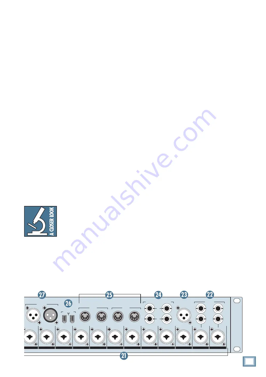
21. MIC/Line Inputs
These are Neutrik combo connectors, which accept
balanced microphone inputs from an XLR connector or
balanced line-level inputs from a 1/4" TRS connector.
The microphone preamps feature our new Onyx design,
with higher fidelity and headroom rivaling any stand-
alone mic preamp on the market today.
The XLR inputs are wired as follows:
Pin 1 = Shield or ground
Pin 2 = Positive (+ or hot)
Pin 3 = Negative (– or cold)
The 1/4" inputs are wired as follows:
Sleeve = Shield or ground
Tip = Positive (+ or hot)
Ring = Negative (– or cold)
22. INSERTS
These 1/4" TRS jacks provide a send and return point
for channels 1-2. Use the CHANNEL INSERT jacks to
connect serial effects devices such as compressors,
equalizers, de-essers, or filters to each individual channel.
The INSERT points are after the GAIN controls, and
just before the analog-to-digital converters. The SEND
output is low-impedance, capable of driving any device.
The RETURN is high-impedance and can be driven by
almost any device.
Tip:
Since the inserts are before the A/D converters, it’s
a good place to strap a compressor on an unruly singer
to avoid overloading the A/D converter without having
to turn down the GAIN control a whole bunch.
17. Output Level BYPASS
Turn the BYPASS switch on to remove the OUTPUT level
control from the signal path. This ensures that the signal
at the eight balanced line-level outputs is the same as the
DAW’s source channels. The indicating LED next to the
BYPASS switch lights when the bypass function is on. This
might be useful for sending a two-channel mix to a record-
er, or for using these outputs (along with some line-level
inputs) as sends to a signal processor during mixdown.
18. MONITOR Level Control
Use this knob to adjust the signal level at the CON-
TROL RM MONITOR jacks on the rear panel. It adjusts
the signal for both the left and right Control Room Moni-
tor outputs, ranging from off (
∞
) to unity gain (MAX).
Connect the CONTROL ROOM MONITOR outputs di-
rectly to the inputs of a pair of powered studio monitors.
No mixer required!
19. MONITOR A/B Select Switch
Use this button to select the CONTROL RM MONI-
TOR A or CONTROL RM MONITOR B outputs [24]. The
LEDs next to the switch indicate whether Output A or
B is selected. The MONITOR Level Control [18] acts on
whichever Monitor output is selected.
Note:
This function is duplicated with the MON A/B
FOOTSWITCH jack on the rear panel.
When connecting two pairs of control
room monitors to the Onyx 1200F, it is
most effective to balance the sensitiv-
ity of the monitors so that they are
the same loudness when switching
between the two pairs. Active moni-
tors usually have a sensitivity control on the rear panel.
Passive monitors can be adjusted using the power
amplifier level controls.
20. Power Switch
This is self-explanatory. When the POWER switch is
turned ON (up), power is supplied to the Onyx 1200F.
~100-240 VAC
50-60Hz 45W
FOOTSWITCH
TALK
BACK
MON
A/B
ADAT
IN
OUT
1
2
SEND
RETURN
MIDI 1
IN
OUT
MIDI 2
IN
OUT
EXTERNAL
WORD CLOCK
IN
OUT
TALKBACK
MIC
(48V)
A
B
OUT
S/PDIF
IN
8 CHANNEL BALANCED
LINE LEVEL OUTPUT
12
11
10
9
8
7
6
5
4
3
2
1
AES/EBU
OUT
IN
FIREWIRE
ON
YX MIC PRE
ON
YX MIC PRE
ON
YX MIC PRE
ON
YX MIC PRE
ON
YX MIC PRE
ON
YX MIC PRE
ON
YX MIC PRE
ON
YX MIC PRE
ON
YX MIC PRE
ON
YX MIC PRE
ON
YX MIC PRE
ON
YX MIC PRE
CONTROL RM MONITORS
L
2
1
R
INSERTS
(BALANCED)


