background image

6. 

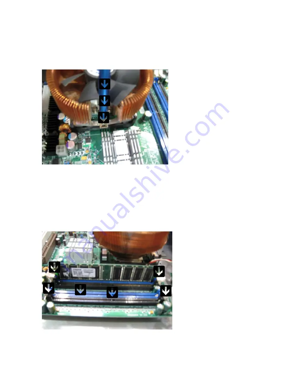
Take the processor heat sink and place it over the


processor. Orient the heat sink screw 

holes so they align with the screw holes on the mounting brackets. Take the heat sink 
bracket screws and place them in the screw holes. Slowly tighten the screws on each 
side of the heat sink. Note: you will need to rotate the heat sink fan until you can fit a 
screw driver between the fans blades above the screw holes. 


7. 

Now it is time to install your RAM modules. It is very important you install one RAM 
module in A1 and the other in A2. RAM socket A1 and A 2 are colored blue. Slowly move 
each latch outwards at the end of Ram socket A1 and A2. Take your first RAM module 
and place in socket A1. You will feel a small amount of resistance when pushing down 
on the RAM module. Push until you see and feel the latch at each end snap into place. 
Repeat the process for the second RAM module in socket A 2.


!

 Note:

 Keep each 

RAM module in a safe place away from any potential electro-static 

discharge until you are ready to use the specific RAM module. 


Содержание DIGITAL XBUS - SOFTWARE

Страница 1: ...Instructions before proceeding Keep the new motherboard in its protective anti static bag until the exact moment you are ready to use it This repair requires opening your Digital X bus and handling se...

Страница 2: ...ed to extend beyond the rear side of the Digital X Bus by at least three feet or one meter of distance because the rear panel will eventually slide out like a drawer and you will need to make sure it...

Страница 3: ...r are already familiar with how to open the Digital X bus properly 1 Start by removing the aluminum cross brace This will be held in place by 5 Philip head screws located in each corner of the brace a...

Страница 4: ...socket 3 Remove the flat IDE ribbon cable located in the upper right hand corner Note this will be a blue header labeled IDE1 4 Next we will remove the ribbon cabled used to connect the USB from the...

Страница 5: ...ort to Com 2 port of the Iwill motherboard Start by removing the end of the ribbon cabled connected to the Iwill motherboard refer to figure 5 below Leave the other end of the ribbon cable connected t...

Страница 6: ...away from any potential electro static discharge 7 Now it is time for the most important part Take the Digital X bus PCI card is located in PCI slot 5 Slowly pull the PCI card upwards away from the P...

Страница 7: ...ach screw holding the heat sink As you loosen each screw you will feel the spring action start to release Once the heat sink screws are free from the heat sink slowly twist and slide the heat sink off...

Страница 8: ...the arm located on the side of the processor socket Slowly lifts the processor from the processor socket make sure you do not feel any resistance the processor should come free very easily Note Set t...

Страница 9: ...t is time to remove the Iwill motherboard The motherboard is held in place by 9 screws Remove all 9 screws then lift the Iwill motherboard from the stand offs Place all 9 screws in a safe place for la...

Страница 10: ...rist Strap 2 Place the new motherboard in the position of the previous Iwill motherboard Make sure to align the new motherboard on top of the stand offs Bring the new motherboard all the way to the fr...

Страница 11: ...cessor s socket Note be very carful when handling the processor keep the processor away from any potential electro static discharge Note make sure to put a small amount of thermal paste on the process...

Страница 12: ...t is time to install your RAM modules It is very important you install one RAM module in A1 and the other in A2 RAM socket A1 and A 2 are colored blue Slowly move each latch outwards at the end of Ram...

Страница 13: ...lot figure 9 below Tilt the AGP video card backwards towards the rear of the AGP slot Slowly lower the front of the AGP video card into the AGP slot Once the AGP video card is in position in place pre...

Страница 14: ...talled in the correct orientation in regards to pin 1 otherwise there could be damage to the motherboard Take the side of the MIDI Footswitch conversion cable labeled motherboard and connect it to gam...

Страница 15: ...e of the Digital X Bus daughter board and connect it to USB header 6 7 You will need to make sure to position the red strip on the ribbon cable indicating pin 1 so that it is facing the motherboard ba...

Страница 16: ...daughter board to the Supermicro motherboard Take the10 pin ribbon cable located on the right hand side of the of the Digital X Bus daughter board figure 15 below and connect it to Com port 2 on the S...

Страница 17: ...d drive and back plain Carefully take the Digital X Bus PCI card and position it over the fifth PCI slot Push down slowly on the PCI card until it is firmly seated all the way Note Be very careful not...

Страница 18: ...e IDE ribbon cable This cable will connect to IDE 1 The IDE 1 header is colored blue 14 Connect the 20 pin Molex connector to the primary power supply header 15 Connect the 4 pin 12V power supply cabl...

Страница 19: ...ce so the screw holes line up with PCI card and mounting brackets Take 4 of 5 screws we sat aside earlier and begin tightening down each corner of the cross brace Once the cross brace is loosely in pl...

Страница 20: ...ure 22 18 The last thing we will need to do is install the momentary power switch Take the momentary power switch and connect it to the PW ON jumper The PW ON jumper will be located in the upper right...

Страница 21: ...oot and allow you to recover any stored session files the system is not stable You can use an external USB flash drive to transfer and backup a stored session files You will require a copy of the Digi...

Страница 22: ...A IDE Channel 0 Master Auto Access Mode Auto IDE Channel 0 Slave None IDE Channel 1 Master None IDE Channel 1 Slave None Halt on No Errors Base Memory 640K Extended Memory 1047552K Total Memory 10485...

Страница 23: ...KB Wake up from S3 Disabled AC97 Disabled CPU THRM Throttling 75 0 I O Device Configuration Onboard Serial Port 1 3F8 IRQ4 Onboard Serial Port 2 2F8 IRQ3 UART Mode Select Normal X RxD TxD Active Hi L...

Страница 24: ...m only Processor Clock Option Limit CPUID MaxVal Disabled Hyper Threading Technology Enabled Spread Spectrum Disabled CPU Clock 200MHz SECURITY Set Supervisor Password Disabled will not show option Se...

Страница 25: ......

Отзывы: