background image

2. INSTALLATION & CONFIGURATION 

This section provides complete instructions for mounting the  
MacFi-se, MP3 Digital Audio Record / Play System on a wall or 
table. It also illustrates all interface requirements to auxiliary 
equipment, including inputs and outputs. Configuration switch 
settings are provided. 

2.1 Installation Steps 

These are the general steps for installation. 
 
1. Find a space on the wall or table. For table top applications, 
install included rubber feet. Allow approximately 6 inches in front 
of both sides of the unit for user access to the controls and 
wiring. 
2. Mount the unit to the selected place with its wiring at least 18” 
away from power supply or other equipment that generates 
electrical noise. 
3. Set DIP switches to the desired operation. 
4. Connect audio inputs and outputs. 
5. Connect control inputs and outputs.  
6. If using the optional power supply, make sure there is a 
standard, non-switched electrical outlet available. 
7. Connect and apply power. 
8. Test unit operation. 

2.2 Hardware Configuration 

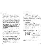
2.2.1. Power Connector 


Two terminal pluggable connector. 
1  12 VDC at 1 amp 
2  Ground


Power LED


Green LED which indicates 

that power is supplied to the 

unit and operating correctly 

Off 

No power supplied to unit 

On 

Power on, system OK 


3.3 Playing-Local 

Local playback is achieved through the LED’s and buttons located 
on the front side of the MacFi-se unit. Please reference the 
Manual Button & LED Configuration section of this manual for 
additional information on functions.  
 
Step 1 

– Make all desired power, audio out, configuration switch 

and I/O connections to the unit and power up. Unit will initiate 
self test and default to idle mode. 

Step 2 

– Use Select button to determine message location to play. 

Select button will only increment between valid message 
locations, showing them on the Message Number Display. 
System will scan/blink through all segments on the Message 
Number Display and exit if no valid messages exist when Select 
button is depressed. 

Step 3 

– Depress Start/Stop button to begin playback. Message 

LED will remain solid during playback. 

Step 4 

– Depress Start/Stop button to end playback and return to 

idle. 

 
Playback message selection will time out after 1 minute of 
inactivity. Default message is the first location with a valid 
recording. 

3.4 Playing-Remote Control 

Remote Control playback is achieved through the I/O connections 
located on the rear side of the MacFi-se unit. This process is only 
applicable to the first eight messages on the system. Please 
reference the Hardware Configuration section of this manual for 
additional information on available connections. Playback of 
message will include selected repeat and delay parameters.


21 


Содержание MacFi-se

Страница 1: ...andwidth and memory configurations are available Page Stacker Feedback Eliminator Mackenzie s OPM series of Digital Page Stacker Repeater and Feedback Eliminators offer advanced features for the most...

Страница 2: ...nnected from both power and the rest of the phone system 11 Use Caution when installing or modifying configuration switches or control lines 12 The unit must be securely attached to a wall board rack...

Страница 3: ..._______________________________________________________________ __________________________________________________________________ Table of Contents 1 OVERVIEW 5 1 1 Features and Capabilities 5 Genera...

Страница 4: ...e proof of the date of original purchase In the event you need to ship your MacFi se system to the factory for service call us for a return authorization number When you ship your MacFi se system you...

Страница 5: ...007 FAX No 909 394 9411 1 OVERVIEW 1 1 Features and Capabilities The Mackenzie MacFi se family is the most cost effective series of MP3 Digital Audio Record Play Systems available for industrial usage...

Страница 6: ...ushbuttons Record Start Stop Select Sync LED s Display Overdrive Audio Sense Record Status Sync LED s message number display 4 MacFi se SERIAL PORT CONTROL The MacFi se includes an RS 232 Serial contr...

Страница 7: ...tor remains ON at which time it may be released Record Indicator will remain ON and Status Display will read FC while system runs audio memory check This process could take several minutes Step 3 Wait...

Страница 8: ...system OK 3 3 Playing Local Local playback is achieved through the LED s and buttons located on the front side of the MacFi se unit Please reference the Manual Button LED Configuration section of this...

Страница 9: ...e mode Step 2 Provide a maintained input signal between the Record Input and common this will blink the Record LED Step 3 Provide a maintained input signal between the message activation input desired...

Страница 10: ...for subsequent message activations Other play activations will be serviced normally even with another input held active indefinitely This mode supports message queuing Message queuing allows the user...

Страница 11: ...nce the queue is filled will be ignored A stop command will stop the message which is currently playing and when released the next message in queue will begin playing If multiple inputs are held activ...

Страница 12: ...lay Relay Output Normally Open 2 3 2 Audio Sense Indicator This green LED monitors the presence of audio on recording input This is designed to indicate that the audio level is optimum for system perf...

Страница 13: ...This red LED monitors the level of the recording input Overdriving the system will cause audio to clip adversely effecting sound quality Monitor the input material and set the input level just below o...

Страница 14: ...14 15...

Отзывы: