TOPRHWS Hardware Manual
M
2
I Corporation
11-35, Simin-daero 327beon-gil, Dongan-gu, Anyang-si, Gyeonggi-do, 14055,Republic of Korea
7 / 19
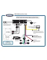
번호
Name
Description
Remarks
①
Power Input
24V DC Power Input
②
Ext. Function Connector
EMG S/W, 3-POS S/W, KEY-Lock, Function1~6
③
Communication
ETHERNET, RS232C/422/485
Cannot be used simultaneously
④
Power S/W
TOPRHWS Operating Switch
⑤
TOPRH Connector
Connector to TOPRH0700WD FE
Produced separately
Chapter 5 Interface with Other Devices
Communication of the product with external devices requires a connection that meets following conditions.
5.1 Serial Communication Specifications
5.1.1 RS-232C
Items
Contents
Protocol
Full Duplex
Synch.
Asynchronous
Communication distance
About 15m
Type of connection
1:1
Control code
ASCII Code or HEXA Code
Baud rate
2400,4800,9600,19200,38400,57600,76800,115200 bps
Data type
Data Bit
7, 8 bit
Parity Bit
NONE, ODD, EVEN Parity
Stop Bit
1, 2 bit
5.1.2 RS-422/485
Items
Contents
Protocol
Full Duplex, Half Duplex
Synch.
Asynchronous
Communication distance
About 500m
Type of connection
1:N (N ≤ 31)
Control code
ASCII Code or HEXA Code
Baud rate
2400,4800,9600,19200,38400,57600,76800,115200 bps
Data type
Data Bit
7, 8 bit
Parity Bit
NONE, ODD, EVEN Parity
Stop Bit
1, 2 bit
5.1.3 COM1 Connector pin number and Signal names
TYPE
PIN No.
Signal
Direction
Contents
9Pin Female
1
RDA(RD+)
Input
RS-422/485 Receive Data(RX+)
2
RD(RxD)
Input
RS-232C Receive Data
3
SD(TxD)
Output
RS-232C Send Data
4
RDB(RD-)
Input
RS-422/485 Receive Data(RX-)
5
SG
-
Signal Ground
6
SDA(SD+)
Output
RS-422/485 Send Data(TX+)
7
NC
NC
8
NC
NC
9
SDB(SD-)
Output
RS-422/485 Send Data(TX-)