


M3LU
5-2-55, Minamitsumori, Nishinari-ku, Osaka 557-0063 JAPAN
Phone: +81(6)6659-8201 Fax: +81(6)6659-8510 E-mail: [email protected]
EM-2652-A Rev.2 P. 6 / 9
■
OUTPUT TYPE (SW2 & 1)
Table 10
OUTPUT
SW2-8
SW2-7
SW1-4
SW1-3
SW1-2
SW1-1
0 – 20 mA
OFF
OFF
OFF
ON
OFF
OFF
-2.5 – +2.5 V
OFF
ON
ON
OFF
OFF
ON
-10 – +10 V
ON
OFF
ON
OFF
ON
OFF
■
OUTPUT TYPE / PC CONFIG (SW1)
Table 11
OUTPUT
SW1-4
SW1-3
SW1-2
SW1-1
0 – 20 mA
OFF
ON
OFF
OFF
-2.5 – +2.5 V
ON
OFF
OFF
ON
-10 – +10 V
ON
OFF
ON
OFF
CHECKING
1) Terminal wiring: Check that all cables are correctly con-
nected according to the connection diagram.
2) DIP SW setting: Check that the switches are set to ap-
propriate positions.
3) Power input voltage: Check voltage across the terminal
10 – 12 (AC) or 11 – 12 (DC) with a multimeter.
4) Input: Check that the input signal is within 0 – 100% of
full-scale.
If the thermocouple, RTD, potentiometer, resistance or
their extension wires are broken, the output goes over
100% (below 0% with downscale protection) due to burn-
out function. Confirm the status indicator LED pattern
and check leadwires in such a case.
5) Output: Check that the load resistance meets the de-
scribed specifications.
I/O RANGING & FINE ADJUSTMENTS
After the DIP SW setting is complete, set up the precise
input and output range using the front control buttons. Be
sure that the front control button function is enabled with
the DIP switch setting.
The front LEDs’ colors and blinking patterns help you to
easily identify the transmitter’s status and confirm the set-
up actions in each step of Calibration Modes. Please read
the following explanations referring to “Calibration Flow
Chart”.
■
PREPARATION (e.g. M3LU-R4/A, DC powered type)
1) Mount the DIP-SW-configured M3LU on to a DIN rail.
2) Connect the M3LU to a simulator and a multimeter and
to a DC power source as shown below.
3) Turn the power supply on and wait for 10 minutes.
3
5
7
8
11
12
M3LU
Multimeter
Simulator
+
–
Power Source
+ –
+
–
Example with V/mA input.
See Connection Diagram
for other input types.
Example with
DC power.
■
INPUT & OUTPUT RANGING
[Example] Setting both input and output to 1 – 5 V DC
1) Run Mode: Confirm that the green LED is blinking (mod-
el M3LU-x/A) or the green LED turns on (model M3LU-
x/B).
2) Input Ranging Mode: Hold down MODE button for longer
than 5 seconds until the LD1 red LED is ON and the LD2
red LED is blinking.
3) 0% Input Ranging: Apply the desired minimum input
level (e.g. 1 V) from the simulator and hold down DOWN
button until the LD1 blinks for approx. 2 sec. and then
turns OFF. When you release the button, the LD1 is re-
turned to ON.
The blinking LD1 means that the value is stored in the
memory. If the LED does not change, the entered level
may be inappropriate: too small a span, or out of usable
range (same for all steps).
4) 100% Input Ranging: Apply the desired maximum input
level (e.g. 5 V) from the simulator and hold down UP but-
ton until the LD1 blinks for approx. 2 sec. and then turns
OFF. When you release the button, the LD1 is returned
to ON.
5) Output Ranging Mode: Press MODE button and confirm
that the LD3 red LED instead of LD2 is blinking.
6) 0% Output Ranging: Increase or decrease the simulated
input until the meter shows the desired minimum output
level (e.g. 1 V). Hold down DOWN button until the LD1
blinks for approx. 2 sec. and then turns OFF. When you
release the button, the LD1 is returned to ON.
7) 100% Output Ranging: Increase or decrease the simu-
lated input until the meter shows the desired maximum
output level (e.g. 5 V). Hold down UP button until the
LD1 blinks for approx. 2 sec. and then turns OFF. When
you release the button, the LD1 is returned to ON.
8) Run Mode: When calibration is completed, press MODE
button once and confirm that: the LD1 green LED is
blinking in case of M3LU-x/A; and the LD1 green LED is
ON in case of M3LU-x/B.
■
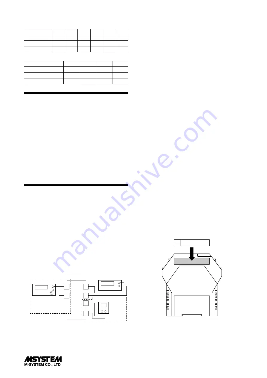
I/O RANGE LABEL
Blank I/O range labels are included in the product package.
Write in the configured ranges and put the label on the side
as shown below.
INPUT
OUTPUT
I/O Range Label (included in the product package)


