53U
5-2-55, Minamitsumori, Nishinari-ku, Osaka 557-0063 JAPAN
Phone: +81(6)6659-8201 Fax: +81(6)6659-8510 E-mail: [email protected]
EM-6485-B Rev.21 P. 35 / 52
■
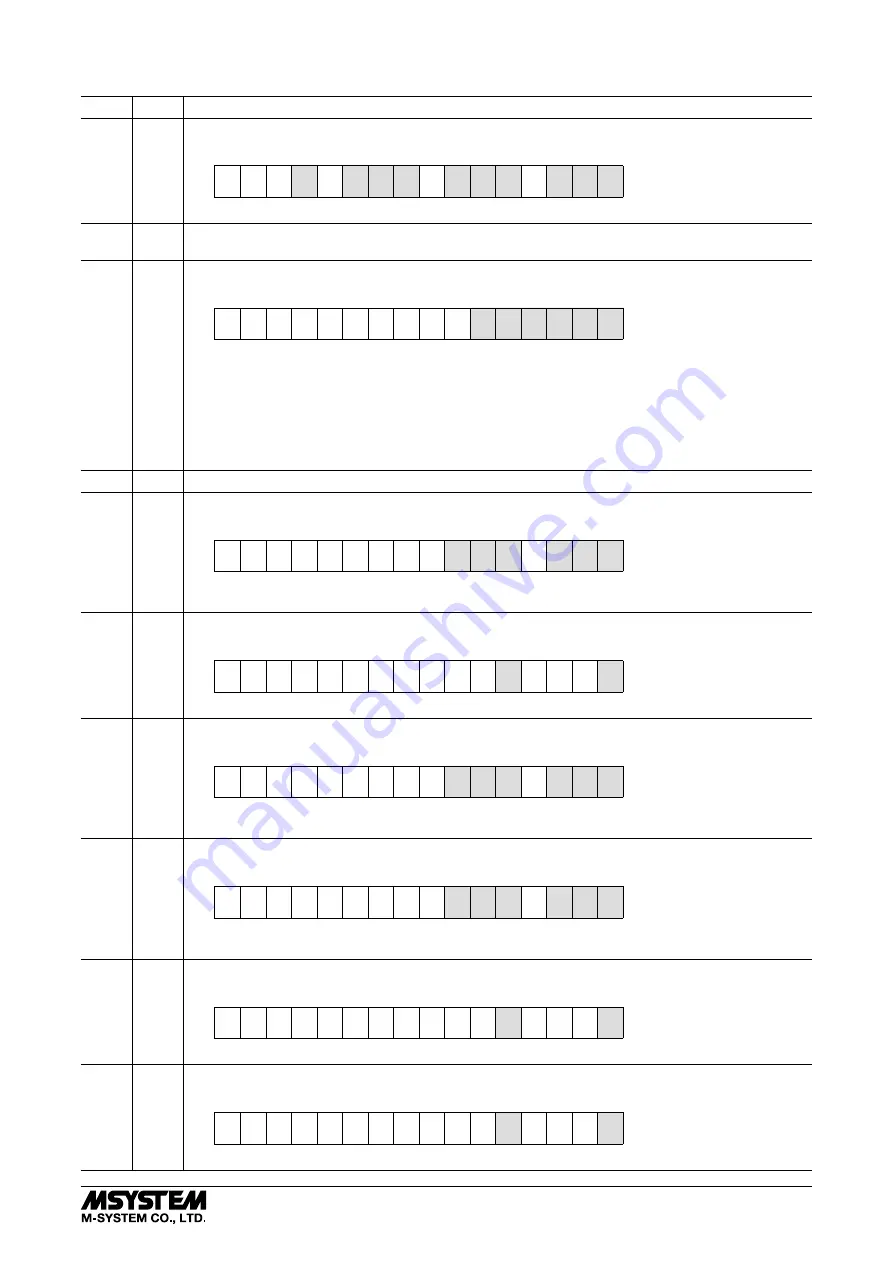
ERROR, ALARM
ADDR. WORD PARAMETER
8001
1
Overload input
Bit assignment as shown below.
Bit
15
14
13
12
11
10
9
8
7
6
5
4
3
2
1
0
F
U31 U23 U12
U3N U2N U1N
l3
l2
l1
‘1’ is placed when the respective inputs are overload.
8002
1
Number of alarm trips
Shows number of alarms presently triggered.
8003
1
System error
Bit assignment as shown below.
Bit
15
14
13
12
11
10
9
8
7
6
5
4
3
2
1
0
STAT AVG ENE SET FDT PRG
PGR : Control software error
FDT : Factory calibration data error
SET : User setting data error
ENE : Energy data error
AVG : Average data error
STAT : Maximum / minimum data error
‘1’ is placed when the respective errors are detected. All measuring operations stop while one or more system
errors are detected.
8004
1
Reserved
8005
1
I1 thr. I3 - Current : Alarm
Bit assignment as shown below.
Bit
15
14
13
12
11
10
9
8
7
6
5
4
3
2
1
0
l3
HI
l2
HI
l1
HI
l3
LO
l2
LO
l1
LO
‘1’ is placed when the respective values are out of the predetermined ranges. ‘0’ in all bits means that no alarm
is tripped.
8006
1
IN - Neutral current : Alarm
Bit assignment as shown below.
Bit
15
14
13
12
11
10
9
8
7
6
5
4
3
2
1
0
IN
HI
IN
LO
‘1’ is placed when the value is out of the predetermined range. ‘0’ in all bits means that no alarm is tripped.
8007
1
U12 thr. U31 - Delta voltage : Alarm
Bit assignment as shown below.
Bit
15
14
13
12
11
10
9
8
7
6
5
4
3
2
1
0
U31
HI
U23
HI
U12
HI
U31
LO
U23
LO
U12
LO
‘1’ is placed when the respective values are out of the predetermined ranges. ‘0’ in all bits means that no alarm
is tripped.
8008
1
U1N thr. U3N - Phase voltage : Alarm
Bit assignment as shown below.
Bit
15
14
13
12
11
10
9
8
7
6
5
4
3
2
1
0
U3N
HI
U2N
HI
U1N
HI
U3N
LO
U2N
LO
U1N
LO
‘1’ is placed when the respective values are out of the predetermined ranges. ‘0’ in all bits means that no alarm
is tripped.
8009
1
P - Active power : Alarm
Bit assignment as shown below.
Bit
15
14
13
12
11
10
9
8
7
6
5
4
3
2
1
0
P
HI
P
LO
‘1’ is placed when the value is out of the predetermined range. ‘0’ in all bits means that no alarm is tripped.
8010
1
Q - Reactive power : Alarm
Bit assignment as shown below.
Bit
15
14
13
12
11
10
9
8
7
6
5
4
3
2
1
0
Q
HI
Q
LO
‘1’ is placed when the value is out of the predetermined range. ‘0’ in all bits means that no alarm is tripped.


