Configuring Applications to Use BiPort 2x4s
Once the drivers for the BiPort 2x4s have been installed, you will need to
configure your MIDI applications to take advantage of the BiPort 2x4s
drivers. The manner in which each application does this is different, so
it is impossible to go over all possible scenarios here. However, most
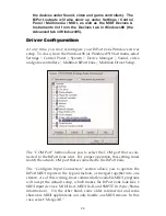
Windows MIDI applications have a MIDI configuration or settings dia-
log box (sometimes called “MIDI Devices” or “MIDI Tools”) that speci-
fies the MIDI input and output devices the program will be communi-
cating with. If your BiPort 2x4s drivers are properly installed, you
should see the BiPort 2x4s MIDI and SMPTE ports listed in this dialog
box.
In its factory default configuration, the BiPort 2x4s looks like eight inde-
pendent devices, 3 of which are inputs and 5 are outputs. From the
application’s configuration dialog, these devices are:
Inputs
BiPort 24s Input A
BiPort 24s Input B
BiPort 24s Sync/Status
NOTE: If the inputs are set up in the driver to be merged, you will see
only one BiPort MIDI input device: “BiPort 24s In A+B+S”.
Outputs
BiPort 24s Output A
BiPort 24s Output B
BiPort 24s Output C
BiPort 24s Output D
BiPort 24s Control
Inputs A and B correspond to the physical MIDI In connectors A and B,
and the SMPTE/Status corresponds to the 1/4” SMPTE Input connector.
Outputs A through D correspond to the physical MIDI Out connectors A
through D, and the SMPTE Control corresponds to the SMPTE processor
command port. Although the SMPTE/Status driver transfers time code
data (MIDI Time Code to be specific) into the program, the SMPTE
Control driver does not actually transfer SMPTE data out of the pro-
gram. Instead, it is used by applications like the Remote Control to con-
figure and control (Start Writing, Stop Writing, User Bits, SMPTE format,
etc.) the processor that resides inside the BiPort 2x4s. If you wish to
transmit MTC through the BiPort, do it through one of the MIDI output
devices.
35


