background image

LX9000 Version 2.6 


September 2011 


Page 39 of 130 

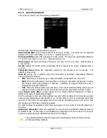
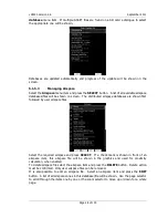
The colour for aircraft that are less than 100 meters below or above your current altitude is 
defined by the 

Near Colour

 item. 

When a signal from a particular aircraft is lost the aircraft remains blinking on the screen for 
the duration defined in the 

Lost device after

 item (default 120 seconds).  After that time 

the aircraft symbol will not be displayed. 
If the 

show labels

 item is checked aircraft altitude and vertical speed are displayed next to 

the aircraft symbol.  The user can modify size, font style and colour.  Select the 

Font style 

and  color

  item.    Use  the  lower-left  knob  to  modify  colour  and  the  lower-right  knob  to 

modify style. 
It  is  possible  to  display  the  flown  path  of  tracked  aircraft.   

Path  colour

  and 

Path  width


define width and colour of paths.  To enable paths check the 

Show paths

 item. 

Содержание LX9000

Страница 1: ...000 Including the LX9000D Rear Seat Device Variometer and GPS Navigation System Version 2 6 LXNAV d o o Kidričeva 24a 3000 Celje Slovenia tel 386 592 33 400 fax 386 599 33 522 info lxnav com www lxnav com ...

Страница 2: ......

Страница 3: ...otary Switches Knobs 13 4 2 Switching on the Unit 14 4 3 User Input 14 4 3 1 Text Edit Control 15 4 3 2 Masked Text Edit Control 15 4 3 3 Spin Control 16 4 3 4 Selection Control 16 4 3 5 Checkbox and Checkbox List 16 4 3 6 Colour Selector 16 4 3 7 Font Selector 17 4 4 Switching off 18 5 Operating Modes 20 5 1 Setup Mode 22 5 1 1 QNH and RES 22 5 1 1 1 QNH 22 5 1 1 2 Safety Altitude 22 5 1 1 3 Magn...

Страница 4: ... Hardware 49 5 1 12 1 Vario Settings 50 5 1 12 2 Vario Indicator Setup 51 5 1 12 3 Flarm 55 5 1 12 4 Compass 56 5 1 12 5 Rear Seat or Front Seat 57 5 1 12 6 AHRS 58 5 1 12 7 NMEA Output 58 5 1 12 8 Engine Noise 58 5 1 13 Polar and Glider 59 5 1 14 Profiles and Pilots 60 5 1 15 Language 63 5 1 16 Passwords 63 5 2 Information Mode 64 5 2 1 GPS Status Page 64 5 2 2 Position Report 65 5 2 3 Satellite ...

Страница 5: ...em 94 6 1 2 Smart vario on other vario systems 94 6 2 Altimeter 95 6 2 1 IGC Barograph Recalibration Procedure 95 6 3 Speed Command 95 7 Flying With the LX9000 96 7 1 On the Ground 96 7 1 1 Power on Procedure 96 7 1 2 Profile Selection 96 7 1 3 Set Elevation and QNH 97 7 1 4 Preflight Check 97 7 1 5 Preparing a Task 98 7 1 5 1 Assigned Area Tasks AAT 98 7 2 Flying a Task 100 7 2 1 Starting a Task ...

Страница 6: ...stacles 116 10 1 5 Uploading FlarmNet Files 117 10 2 Rear Seat Device LX9000D 118 10 2 1 Data Exchange 118 10 2 2 Cable Wiring 119 10 3 ADSB Receiver TRX 1090 120 10 3 1 Installation 120 10 4 AHRS 122 10 4 1 Installation 122 10 4 2 Level adjustments 123 10 5 Compass Module 124 10 5 1 Installation of the Compass Module 125 10 5 2 First Test After Installation 125 10 5 3 Adjusting the Compass Module...

Страница 7: ...t fail in normal use Such repairs or replacement will be made at no charge to the customer for parts and labour provided that the customer shall be responsible for any transportation cost This warranty does not cover failures due to abuse misuse accident or unauthorised alterations or repairs THE WARRANTIES AND REMEDIES CONTAINED HEREIN ARE EXCLUSIVE AND IN LIEU OF ALL OTHER WARRANTIES EXPRESSED O...

Страница 8: ...SD card Barogram calibration chart GPS antenna Flarm Antenna Hex key Inbus 2 2 LX9000 without Flarm Option LX9000 digital unit LXNAV V5 vario unit Main power cable for digital unit Cable for vario unit SD card Barograph calibration chart GPS antenna Hex key Inbus 2 3 LX9000D LX9000D Main power cable RS485 cable 4 meter RS485 splitting unit Vario indicator with cable SD card Hex key Inbus ...

Страница 9: ...the LX9000 digital unit over the RS485 system bus Optionally additional vario indicators and a wide range of interface devices can be daisy chained using the RS485 bus 3 1 1 Display Unit Features Extremely bright 5 6 14 3 cm colour display readable in all sunlight conditions with backlight automatically adapted using an ambient light sensor ALS Using Linux operating system not CE Windows ensures f...

Страница 10: ... into the LX9000 digital unit All necessary connectors are available on the rear side of the unit Flarm external indicator Flarm antenna which guaranties the same comfort as with the original Flarm devices It is very important to point out that the whole system uses only one GPS receiver and therefore offers a low power solution One bicolour LED Flarm External display is included in the delivery e...

Страница 11: ... Please note that altitude data will be sent from the simulator which means that real final glide training will be possible 3 1 5 Technical Data Power input 10 24 V DC Consumption at 12 V o 250 mA minimum brightness without audio and options o 260 mA minimum brightness without audio and with Flarm o 470 mA maximum brightness without audio and options o 480 mA maximum brightness without audio and w...

Страница 12: ...manual all screenshots are given for portrait orientation of the LX9000 However all functionality is the same in landscape orientation 4 1 Rotary Switches and Buttons The following controls are mounted on the front face of the LX9000 digital unit Four rotary selector knobs Eight push buttons SD card reader 4 1 1 Landscape orientation VOLUME selector MODE selector SD Card reader ZOOM selector PAGE ...

Страница 13: ...as four rotary knobs Each has a single function with the exception of the zoom knob which has in some cases a function other than zoom With the upper left rotary knob the volume can be adjusted The upper right rotary switch is the mode selector it changes the mode of the operation At the lower right is the up down switch which is used for selecting sub pages sub menus and editing menus At the lowe...

Страница 14: ...ot procedure is completed the profile selection dialogue is shown Please refer to Chapter 7 1 for more details about starting up the LX9000 4 3 User Input The LX9000 user interface consists of many dialogues which have different input controls They are designed to make input of names parameters etc as easy as possible Input controls can be summarised as Text editor Masked text editor Spin controls...

Страница 15: ...s it to toggle modes Abc mode will start every new word with a capital letter subsequent letters will be lower case ABC mode will enter only upper case letters abc mode will enter only lower case letters Pressing the DELETE button will delete the character at current cursor position Continually press the DELETE button to delete all characters after the current cursor position Press OK to confirm c...

Страница 16: ... boxes on Windows operating system are used to select a value from list of predefined values Use the page selector to scroll through the list 4 3 5 Checkbox and Checkbox List A checkbox enables or disables a particular parameter Press SELECT to toggle the value If an option is enabled a check mark will be shown otherwise an empty rectangle will be displayed Use page selector to scroll through the ...

Страница 17: ... colour is not transparent 0 all other map items will not be seen through it If a fill colour is 100 only the solid border will be drawn 4 3 7 Font Selector Using the font selector it is possible to define a font colour and style for a selected item Turn the lower right knob page selector to change the font style Text is also rendered in the selected font style Turn the lower left knob zoom select...

Страница 18: ...The OFF message will be displayed and the instrument will shut down When the message appears you must release the power button Method 3 When the button with the OFF symbol is pressed for more than 8 seconds the LX90000 will perform an unconditional shutdown This method is recommended only in case that the LX9000 program hangs and it is not possible to shutdown with methods 1 or 2 If you are using ...

Страница 19: ... LX9000 is switched off via software Never power down the LX9000 using the main power switch The LX9000 is running the Linux operating system and sudden power loss may corrupt the file system If main power is lost for a few seconds during flight the flight recorder will not produce two flights The most important flight parameter altitude will remain which means that the final glide calculations ar...

Страница 20: ...S status altitude flight level and height sunrise and sunset or position report to selectable point or satellite sky view Near Mode displays a list of all landable way points and airports The Navigation modes and statistics mode have additional pages which are accessible by rotating the bottom right knob also called the PAGE selector Three main navigational modes airport waypoint and task mode are...

Страница 21: ...s available at no charge on our web pages See Chapter 5 1 5 2 for more details how to obtain the latest databases In way point navigation mode the user is navigating to way points that were previously loaded and selected in the Files and Transfer menu see Chapter 5 1 5 4 Task navigation mode is used for task creation and manipulation Navigation in this page is exclusively to task points ...

Страница 22: ...le only in the front seat setup menu 5 1 1 QNH and RES Turn the bottom right knob to select the required entry field Press the EDIT button and start editing the value 5 1 1 1 QNH Using this feature it is possible to offset the altitude datum which could have changed due to pressure changes during the flight Since changing the QNH influences the indicated altitude care should be taken when changing...

Страница 23: ...ses the Polar data and MacCready setting to calculate speed to fly and climb rate Vario uses the last four thermals average to compute climb rate and uses this value to calculate speed to fly Avg Speed Vario uses the average ground speed over the last 5 minutes for distance and Vario statistics for climb rate Avg Speed MC uses the average ground speed over the last 5 minutes for distance and MacCr...

Страница 24: ... 5 1 11 If the LX9000 is used in two seat aircraft the name of the co pilot may also be entered There is no setup for glider type Glider type is defined in the Polar and Glider setup see Chapter 5 1 13 There are very few settings for the flight recorder compared to other instruments This is because the LX9000 will record all additional data such as wind speed and vertical speed by default If a new...

Страница 25: ...utomatic change over to vario will happen after approximately 10 seconds Detection of straight flight will cause a changeover to speed command TAS When the TAS exceeds a pre set value The TAS at which switching occurs can be selected in 5 km h steps from 100 up to 160 km h or the equivalent in knots or mph Using Smart vario filter vertical speed can be further filtered Behaviour of filter is diffe...

Страница 26: ...s will occur Default values are tuned to human eyes and do not require change Night mode brightness defines maximum brightness when instrument is operating in night mode In night mode brightness is reduced to very low value to reduce difference between ambient light and device backlit If you want to set the brightness manually uncheck the Automatic brightness control and set the brightness manuall...

Страница 27: ...u CUP files LX navigation DA4 files and Cambridge Winpilot DAT files When selecting DA4 or DAT files way points will be converted to CUP format which is the format used for internal storage of points There is no limitation for the number of way points in a file and or name length Airspace file All types of CUB files are accepted 5 1 5 2 Uploading Airspace and Airports Database LXNAV distributes fr...

Страница 28: ...n first followed by user airspace files Select the required airspace and press SELECT If a check mark is shown in front of an airspace item this airspace file will be shown in the graphics and used for proximity calculation when enabled To delete airspace file select the airspace item and press the DELETE button Delete action must be confirmed Only user airspace files can be removed It is also pos...

Страница 29: ...witched off for all the time OFF today proximity warning is switched off for today only OFF hh mm proximity warning is switched off for 10 minutes If no label is shown airspace is enabled for proximity warnings Press EDIT to edit data for the selected zone Airspace type class and altitude borders can be modified in this dialogue 5 1 5 4 Managing Way Points Select the Waypoints menu item and press ...

Страница 30: ...ed Change the filename if required Press TO USB for saving to the USB stick or press TO SD for saving to the SD card When the compatibility mode flag is checked the file will be saved in DA4 format which can be used with older LX devices LX20 Colibri LX5000 and LX7000 CUP and DA4 also stores tasks Tasks will also be uploaded to the LX9000 This feature is very useful if you wish to prepare tasks on...

Страница 31: ...y has a field called description in which comments or notes of up to 250 characters can be added Modified airport data can readily be exported to the LX9000 as a asapt file and imported to the LX9000 using the standard procedure for database updates see Chapter 5 1 5 2 User modified databases will be assigned as user modified with a version of the database and date of export modification executed ...

Страница 32: ... pilot data and declared task Use this option if you wish to load or save a flight declaration from a file The flight declaration is saved to the LX Navigation HDR file On the screen pilot glider and task information are shown Press the SAVE button to save the declaration onto a SD card or USB stick Press the LOAD button for loading Please note that not all data from the HDR file will be loaded Gl...

Страница 33: ... operating system FAT However sometimes Windows does not format the SD card properly or a new card may not be formatted properly It is recommended to format new SD cards before using with the LX9000 the LX9000 can do this for you Formatting a SD Card will erase the entire contents of the SD card 5 1 6 Graphics This dialogue allows the user to define the appearance of the map in navigational mode S...

Страница 34: ...s optimised to work with high terrain quality If the value off is selected no terrain will be shown only water bodies roads railways and cities The background colour is defined by the Background item The default background is black Colours of terrain can be changed using different terrain colour schemes The following colour schemes are available Mountain is default setting with colours from green ...

Страница 35: ...wer left knob to change the transparency value 100 means completely transparent and only the airspace zone outline will be shown 0 means completely solid not recommended If the Show inactive zones option is checked then airspace zones with proximity warning switched off will be shown Use Show only airspace below to eliminate airspace which is going to be too high for the day For example if the for...

Страница 36: ...lected from following options Name way point name is shown The name length item controls how the name is displayed Code will display the ICAO code or short name Elevation shows way point elevation Arrival altitude shows arrival altitude taking into account current MacCready setting safety altitude and current wind Due to complexity of the calculation it will not take the wind profile into account ...

Страница 37: ... the current position and therefore not enough altitude to reach the target with the current glider settings Press the DEFAULT button to reset these settings back to default 5 1 6 5 Optimization The LX9000 calculates the optimised flown distance according to OLC or FAI rules in real time during flight see Chapter 5 1 9 It calculates the available FAI triangle area which is also called the FAI tria...

Страница 38: ... controls whether all task observation zones are to be displayed or if there is only one then that alone will be shown 5 1 6 7 Flarm LX9000 devices can be equipped with the FLARM module If your instrument is equipped with FLARM this menu will let you to modify presentation of the Flarm radar display Flarm radar is not available if competition or privacy modes are active Refer to Chapter 5 1 12 3 C...

Страница 39: ...m default 120 seconds After that time the aircraft symbol will not be displayed If the show labels item is checked aircraft altitude and vertical speed are displayed next to the aircraft symbol The user can modify size font style and colour Select the Font style and color item Use the lower left knob to modify colour and the lower right knob to modify style It is possible to display the flown path...

Страница 40: ... every few milliseconds when the needle is positive on negative side sound is linear not interrupted Linear negative inverse function to Linear positive Linear sound is linear and non interrupted in full scale range Digital positive similar to Linear positive except frequency is not changing linearly but with larger steps Digital negative inverse function to Digital positive Linear positive only s...

Страница 41: ...inverse function to SC positive SC sound is linear and non interrupted in full scale range SC Mixed for positive relative values the sound represents relative for negative relative values the sound represents SC for that setting it is recommended to set SC needle to relative Freq at 0 defines the tone frequency at 0 m s Freq at 100 defines the tone frequency at full deflection Freq at 100 defines ...

Страница 42: ...le and mixing level between voice and vario sound can be adjusted In the Messages window each item can be set separately Only checked items will be posted to the voice module If voice module is integral part of V5 variometer volume level loudness can be also set with volume rotary knob when messages are being played 5 1 7 3 Alarms The vario unit produces an audio alarm on reaching certain confirma...

Страница 43: ...gue it is possible to describe all types of observation zones Angle12 defines the orientation of the observation zone Available values for Direction are Symmetric which is the most common selection for turn point Fixed which is mostly used for assigned areas Next will orient the observation zone in direction of the outgoing leg This is usually used for start Prev will orient the zone in direction ...

Страница 44: ...ssigned area The AAT checkbox will be automatically checked when Radius1 is greater than 10 km By default navigation to task points will be automatically advanced uncheck Auto next if you do not want to change over to next point when reaching selected point This option will be automatically unchecked when Radius1 is greater than 10 km Use Template if you wish to modify start point and finish zones...

Страница 45: ... free flight optimisation Optimisation will not take into account the 10 km distance between turn points which is required by FAI rules The FAI triangle group defines the rules for FAI triangles and these rules can bend a little if you do not want to fly marginal triangles 5 1 10 Warnings There are three types of warnings available Airspace warnings are shown when approaching a particular airspace...

Страница 46: ...rst warning orange will also be given when you enter an airspace zone buffer but the projected flight is computed to cross it An Airspace warning will be raised in all modes and dialogues A warning for an alarmed zone can be dismissed for a whole day some minutes or just quit Quit means that the message will disappear Use Dismiss for spin to define dismiss time in minutes This time will be shown i...

Страница 47: ...ojection is calculated based on the 20 second average vertical speed and time which is defined in the Time item If the projected altitude is greater than the set altitude an altitude warning will be raised Altitude warnings will be raised in all modes and dialogues just as for airspace warnings Altitude warnings can be dismissed for 1 minute 5 minutes or disabled ...

Страница 48: ...ation to the current object Uncheck appropriate items if you want to disable this part of the message You can also define the way direction to the Flarm object will be presented There are three options Relative bearing In this option direction will be given relative to the glider s nose direction e g Traffic 3 o clock which means traffic is on your right side True bearing Direction is give with ab...

Страница 49: ...ight of water ballast If this option is used the weights of the glider and pilot must be entered Refer to Chapters 5 1 13 and 5 1 2 for more details of how to enter glider and pilot weights 5 1 12 Hardware Use this menu to define hardware properties such as total energy compensation LCD indicators layout compass calibration FLARM module settings AHRS calibration NMEA output and data which will be ...

Страница 50: ...tuned during flight using the following procedure It is essential that this is only done in smooth air it is not possible to tune the TE accurately in turbulent air Set TE compensation to 100 and TE filter to default Accelerate up to approximately 160 km h 75 kts and keep the speed stable for a few seconds Gently reduce the speed to 80 km h 45 kts Observe the vario indicator during the manoeuvre A...

Страница 51: ...emperature OAT sensor With the offset setting it will correct static errors of temperature measurement There is another input called VARIO PRIORITY When this input is activated by grounding the appropriate wire the unit will change over to Vario immediately This input wire is set open not grounded as a factory default on delivery 5 1 12 1 4 Altitude Source The LX9000 has two pressure altitude sens...

Страница 52: ...tes speed altitude in feet or flight levels Speed to fly bar symbol is indicating which speed you have to fly according to current MacCready setting sink rate and speed One arrow means 10units of speed faster or slower Up red arrows mean fly slower and down blue arrows mean fly faster Red diamond symbol shows average vertical speed Blue arrow symbol shows current MacCready value Green T symbol rep...

Страница 53: ...er displayed can be configured separately for Vario mode and SC mode Following parameters can be shown Altitude NN altitude Distance distance to the navigation point Glide diff final glide altitude difference Speed TAS Leg speed speed on leg QNH ft NN altitude in ft Flight levels GPS indicator shows the current GPS status Battery indicator shows the current battery level It will turn re when the b...

Страница 54: ...of Needle Two numerical displays upper and lower Labels and indicators These following functions can be set see next picture Needle vario needle Vario SC Netto or Relative SC Ring Displays speed command at all times Upper Numeric Display Integrator time flight time task remaining time Upper line the parameter displayed can be configured in both Vario and SC modes Vario Mode Indicator Shows current...

Страница 55: ... switched on Privacy ON Flarm unit works in stealth mode Other Flarm units will not receive altitude and vario information concerning your glider For collision warnings this mode has no influence Ext PC Use this mode when you want to receive externally connected Flarm on PC port LOW BATTERY INDICATOR GPS STATUS INDICATOR OFF NO GPS BINKS GPS BAD ON GPS OK LOWER NUMBER DISPLAY NEEDLE SHOWS RELATIV ...

Страница 56: ... mode However if you do not want other aircraft to see you you should switch mode to Privacy ON Reduce warnings will significantly reduced Flarm warnings Use this option if you are flying in gaggles or areas with high density of other aircraft We recommend you sign in at FLARMNET org This is free of charge Registering with FLARMNET allows others to see you not only with Device ID but also with you...

Страница 57: ...he user changes the way point target on other device The message Waypoint target received will be displayed on the screen and you will be navigating to the same way point as other device Please note that it is not necessary to have this way point in your databases as the complete way point information is transferred If the Waypoint checkbox is not checked it is still possible to send a target to t...

Страница 58: ...pable of outputting position data sentences in NMEA format for use by other devices Data is divided into three groups GPS data will output all GPS related data such as time longitude and altitude LX9000 data will output all variometer related data such as vario MacCready and ballast Flarm data will output all Flarm related data The NMEA baud rate will be always 19200 bps any other settings are ign...

Страница 59: ...Glider Use this dialogue to enter glider polar and other glider properties As default polar a standard class glider is selected Polars for most modern gliders are already prepared Press the LIST button and a dialogue with a list of all available gliders will be shown ...

Страница 60: ...n weight corresponds to the min load value and represents the value at which the polar was measured or recalculated Max weight is the maximum takeoff weight allowed for a glider It is not used in the calculation it is just a reminder to the pilot of the maximum takeoff weight Empty weight is weight of the glider without pilot and ballast The overload factor is calculated as weight glider Minimum b...

Страница 61: ...ension Press the LOAD button to load a profile from a SD card or USB stick A profile will be copied to the LX9000 Press the EDIT button to edit the profile name A profile can also be locked This option is very useful for club operation where one does not want a global club profile to be changed When a profile is locked all settings will be read only A profile file can be opened and manipulated wit...

Страница 62: ...LX9000 Version 2 6 September 2011 Page 62 of 130 For more information about LXStyler please refer to the LXStyler manual ...

Страница 63: ...ys information about the LX9000 and its sensors 01049 will perform Auto zero will set vario and speed to zero 30000 browses through installed files use with caution 41000 first or forced update of Flarm 42000 update of Flarm through PC port default 44441 shows debug information 46000 enables disables the co pilot remote stick This option is used if you want to drive a single LX9000 via two remote ...

Страница 64: ...t FLARM status is shown TX means FLARM is transmitting data to others and the number indicates how many other FLARM devices are within range If you press the MARK button a new way point will be created with the current latitude longitude and elevation based on the terrain database The way point name is generated from the current date and time separated by the minus character and preceded by an und...

Страница 65: ...tion about tracked satellites is given on this page If no satellite information is available a message No satellite info is displayed Green satellites are satellites currently being used for position determination Three concentric circles represent satellite elevation 0 30 60 degrees above horizon If a satellite is in the centre of the circles it is directly overhead When you are experiencing bad ...

Страница 66: ...is indicated by the grey background in the header Select the preferred landable place via the lower right knob and press the GOTO button It will automatically change to airport mode and navigation will commence to selected point Duplicates are automatically removed If a target with nearly the same latitude and longitude is found within both the distributed airports database and user way point file...

Страница 67: ...e SD card and or USB stick if it has been inserted into the LX9000 when the message Calculating security is displayed This message appears when landing conditions are met You can also delete a flight using the Files and Transfer menu see Chapter 5 1 5 7 5 4 2 Statistics During Flight Using the lower right knob the user can change the statistics page There are three pages available Flight statistic...

Страница 68: ...utes statistics displays data for the last 60 minutes of flight If the task was started then Dis flown is the distance flown on the task for the last hour otherwise it is the optimised distance If the task distance is used a remark On Task is displayed in the header ...

Страница 69: ...lites Local time shows the local time You can set a different time zone in the Units dialogue see Chapter 5 1 11 The battery symbol indicates status of the battery When the battery is very low the symbol will turn red and also the Low battery warning will be displayed North direction is pointing to true north This is important if map orientation is not north up at the top The airplane symbol in th...

Страница 70: ...glide path Chevrons show the position relative to the required glide path in percent One arrow means 5 above or below final glide In the example more than 25 below glide path is shown The middle number is the current MacCready setting In task mode it is prefixed with the letter T A B G S or AG See chapter 7 2 1 for detailed explanation of this mode Sometimes there will be another number above MacC...

Страница 71: ...to data shown on the previous pages the internal pressure sensor altitude is shown as AltIGC AltInv shows the altitude in opposite units to those defined in the Units setup OAT is the outside temperature Pot Temp is the potential temperature and Battery displays the current voltage The estimated time of arrival and estimated time established are displayed at the bottom part of page Also informatio...

Страница 72: ...remote menu will disappear automatically after 10 seconds if no further action is taken In airport mode the following selections are available Select option is used to select an airport as the new navigational target Mc Bal will set MacCready ballast and bugs see Chapter 5 5 4 2 for more details Map item is used to quickly modify map parameters Wind will open a dialogue where wind changes with alt...

Страница 73: ...de on the rear seat device Night will reduce backlight to level acceptable for flying in very dark conditions Off will switch off the instrument The message LX9000 is shutting down Please wait will be displayed The LX9000 can also be powered off by presssing the upper left button until the message switching off appears 5 5 4 1 Select an Airport There are two methods of selecting filter mode and li...

Страница 74: ...ong the airports Press GOTO once more and you will navigate to it If you do not know the exact name of an airport just select the first letter and press the GOTO button Now scroll to the desired airport using the lower right knob Press the GOTO button once more and you will navigate to the selected airport Press the LIST button to enter list mode In list mode airports are listed as in near airport...

Страница 75: ...n values which are defined in the Units menu see Chapter 5 1 11 You can set the load for an empty glider by pressing the Empty button Pressing the BUGS button will toggle the menu again from Ballast setting to Bugs setting A bug setting is used to set polar degradation due to a dirty wing The input is in percentage degradation of glide ratio 5 means glide ratio degradation is 5 Pressing CLEAN will...

Страница 76: ... Cur trk current track vector Opt dis optimised distance Opt tri optimised triangle FAI area FAI triangle assistant is turned on off A Flarm object may also be hidden because competition mode is on or privacy mode is on Please check these settings if FLARM objects are not visible even if the item is checked It is possible to store map settings for future use There are two memory locations MEM 1 an...

Страница 77: ...t and cannot be modified by the user The wind profile is shown on the left side of the dialogue Yellow coloured altitude indicates our current MSL altitude Using the lower left knob you can scroll up and down through the wind layers Use the EDIT button to manually enter wind data If a new wind direction is entered all wind directions in range from start altitude to end altitude will be modified Th...

Страница 78: ...rk If you press the MARK button a new way point will be created with the current latitude and longitude and elevation based on the terrain database The way point name is generated from the current date and time separated by the minus character and preceded by an underscore Way point data can be modified Refer to Chapter 5 6 1 for more details Press the OK button to save a marked way point or press...

Страница 79: ...lider and pilot The LX9000 is pre loaded with the FlarmNet database to identify known FLARM Device IDs with plane and pilot data You can upload the latest FlarmNet database after downloading it from http www flarmnet org The update procedure is similar to the update procedure for airport databases See Chapter 5 1 5 2 for more details about updates We encourage all users to upload their data to the...

Страница 80: ...ersion 2 6 September 2011 Page 80 of 130 5 5 4 8 Rotate FAI Area This option is used to rotate the FAI triangle assistant to match your suitable position If FAI area is not enabled this option will not be shown ...

Страница 81: ...ity of the current position Mark option is used to mark the current position and create a way point Flarm button will display a list with all visible Flarm objects You can select one and use it for navigational purposes Edit button will edit data for the selected point New button will add new point A new point can also be copied from the airports database Delete button deletes the selected point R...

Страница 82: ... point Press the LON LAT button to toggle back to input of latitude and longitude Modify other attributes at your discretion When finished press the OK button to confirm changes or press CANCEL to dismiss changes The modified way point will be updated in the appropriate file automatically 5 6 2 New Way Point Select this option if you want to add new a way point to the active way points file If no ...

Страница 83: ...d The minimum data that must be entered are name latitude and longitude Press the OK button to confirm changes and create the new way point The new way point is added to active way point file Press the CANCEL button to abandon creation of new point Elevation will be assigned automatically once the position is entered Elevation is taken from digital elevation model which is stored in the LX9000 for...

Страница 84: ... task used for navigation will also be declared in the IGC file Task mode has four pages Use the lower right knob to switch between pages These pages are designed to suit needs for racing tasks as well as for assigned area tasks with minimum task time The first page is identical to first pages of the airport and way point modes It shows navigational data to the current turn point However the final...

Страница 85: ...ad of the button functions Edit action is used to edit the task This is the one and only task that will be declared and will be available for navigation Mc Bal action will set MacCready ballast and bugs see Chapter 5 5 4 2 for more details Move action is used in assigned area tasks to move the navigation point inside the selected assigned area Restart is used to restart a task This action is avail...

Страница 86: ...e creation of tasks as easy as possible Press the MORE button to see more options Available actions are Press the EDIT button to enter a new task point edit an existing one or to enter task time OK action will confirm changes to the task and return to the navigational page CANCEL action will cancel all modifications of the task and return to the navigational page Use the ZONE button to modify the ...

Страница 87: ...he first letter of the task point name using the lower right knob The Helper will show the first way point that matches this letter Press the CHAR button and the cursor will move to the second letter Use the lower right knob to select the second letter If you want to return to the first letter turn the lower left knob anticlockwise Repeat this procedure until your desired point is selected Press t...

Страница 88: ... defines half the width of the line length Use the lower right knob to increase the radius by 0 1 of the selected distance units and the lower left knob to increase the radius by 5 units If Line is not checked the Angle1 parameter will define the basic shape of the observation zone A value of 180 means that the zone is a cylinder and 45 is the classic FAI sector Rotate the lower right knob to incr...

Страница 89: ...he start zone or start line and finish zone The Navigate to nearest point option is very useful and actually a must if a finish cylinder is used with a significantly large radius Enabling this option will calculate the final glide to the edge of the cylinder rather than to the centre of the cylinder There are also several options in this menu which will help competition pilots to have a less stres...

Страница 90: ...t Speed and or Maximum Start Altitude A lot of competitions are limiting the start altitude and or start ground speed The LX9000 helps pilots to cross the start line at the correct altitude with correct ground speed Enter Start alt and or Start gsp to use this option An indication will be shown on the final glide symbol Character A will be displayed before the MacCready value if a start altitude w...

Страница 91: ...he arrival altitude will increase The upper yellow number shows the current ground speed and the chevrons indicate if you have to slow down or you may speed up In the picture above we are 445 meters below the glide to start altitude Our speed is 122 km h and the chevrons show that we can speed up Start speed and start altitude mode is available only if the Navigate to nearest point is checked 5 7 ...

Страница 92: ...ask will be loaded into the active task and the task edit dialogue will be opened It is also possible to delete tasks from the active way point file Press the DELETE button to delete the selected task Tasks can be sorted by start point task distance and task description Press the SORT button to toggle the sort method 5 7 7 Moving a Task Point If at least one observation zone is defined as an assig...

Страница 93: ... LAT button to toggle between the two methods of moving the point When the DIS BRG button is shown the point is moved in the x y directions Use the lower right knob to move the point in the north south direction or rotate the lower left knob to move point in east west direction If the LON LAT button is shown the point is moved in the radial and azimuth directions Radial direction is indicated with...

Страница 94: ...good static pressure source If pneumatic compensation is selected the TE Pst port should be connected to the TE probe 6 1 Smart Vario Description The LX system incorporates two configurable electronic filters in the circuitry The first filter adjusts the time constant and is adjustable between 0 5 and 5 seconds The 0 5 second setting is the fastest while the 5 second setting provides maximum dampi...

Страница 95: ...t the recording interval to 1 second see Chapter 5 1 2 Place it in the chamber and carry out a short climb to about 100 m to start the flight recorder Bring the chamber pressure to exactly 1013 2 hPa Decrease the pressure by 1000 m and hold for about 30 seconds Continue the procedure to 6000 m Increase the pressure in 1000 m steps back to 1013 2 hPa After reaching ground wait about 3 minutes and t...

Страница 96: ... of the Linux kernel operating system then the version of the file system The boot procedure normally takes 30 seconds When completed the profile selection dialogue is shown It is recommended to switch the unit ON some minutes prior to takeoff to give the GPS receiver time enough to acquire satellites The flight recorder will also make a takeoff baseline Longer running on the ground will not reduc...

Страница 97: ... to proper value The QNH button should be pressed only when airfield elevation and QNH pressure are given This might happened on some competitions In all other cases elevation should always match QNH pressure The profile selection and Elevation dialogues are not shown if the LX9000 is switched off and on during flying 7 1 4 Preflight Check After elevation setup the LX9000 will switch to airport mo...

Страница 98: ...ailable in future releases Read way point and task file from SD card and load a saved task Load a similar task and modify it Enter task manually It is very important to check the task prior to takeoff Check the turning points sequence distance between points bearings and total task distance Visually check the task and observation zone geometry in the map view 7 1 5 1 Assigned Area Tasks AAT In fac...

Страница 99: ...LX9000 Version 2 6 September 2011 Page 99 of 130 ...

Страница 100: ...ius1 Max radius 200 km Radius2 Min radius 50 km 7 2 Flying a Task After takeoff the unit will switch to flying mode The pilot will notice this because the statistics page will change from logbook view to flight statistics 7 2 1 Starting a Task Before starting a task in task mode a character S will be displayed on the final glide symbol This indicates that the task has not yet been started The lowe...

Страница 101: ...or crossing the start line The LX9000 will always take the correct time as start time If for some reason you miss the start message you may always start the task by pressing the START button Go to task mode and press any button In the top row the START button is shown Press this button and navigation will be advanced to the next turn point In case you change the task in the air and you are already...

Страница 102: ...be advanced to the next turn point and it will recalculate the task taking the optimal fix as the task point 7 2 4 Entering Assigned Area Most probably when entering an assigned area auto advance is going to be turned off The message Inside zone will be shown and buttons CLOSE and NEXT will appear in the lower row Pressing the CLOSE button will dismiss the inside zone message The task will be auto...

Страница 103: ...G or LON LAT button to toggle between the two methods of moving the point When the DIS BRG button is shown the point is moved in the x y directions Use the lower right knob to move the point in north south direction or rotate the lower left knob to move the point in east west direction If the LON LAT button is shown the point is moved in radial and azimuth direction Radial direction is indicated w...

Страница 104: ... the centre of the cylinder 7 3 Procedure After Landing IGC Regulations require a straight line base line in the barogram at the beginning and end of the flight For this reason that it is essential not to switch the unit OFF immediately after landing but to wait a few minutes First the message Flight will finish in 10 seconds will appear and then the message Calculating security The flight is fini...

Страница 105: ...hods to power down the LX9000 See Chapter 4 4 for details It is important that the LX9000 is switched off via software Never power down the LX9000 using the main power switch The LX9000 is running the Linux operating system and sudden power loss may corrupt the file system ...

Страница 106: ...follows Pstatic Static Ptotal Pitot or Total pressure TE Pstatic Static If the unit is to be configured for pneumatic TE compensation using a TE tube then the connections are TE Pstatic TE tube Pstatic Static Ptotal Pitot or Total pressure If the Ptotal and Static are connected the wrong way around there will be no integrator reading average climb during the flight The LX9000 digital unit is conne...

Страница 107: ...rk anymore The reason is not the defect of 57 mm unit it is due to the hot automatic fuse Turn off the LX9000 system and wait for the automatic fuse to cool down 8 1 Installing the LX9000 Prepare the cut out in the instrument panel according to the drilling template Position the LX9000 digital unit in the cut out in the instrument panel Tighten the LX9000 digital unit with attached 2 5 mm screws W...

Страница 108: ...ected to the RS485 system bus by use of RS485 splitting units Installation of any option is plug and play and therefore requires only mechanical installation work The LX9000 digital unit also powers all devices connected to the bus An automatic fuse built into the LX9000 digital unit prevents damage to the digital unit should a short circuit in the wiring or in some attached device occurs ...

Страница 109: ...emale GND LABEL 12VDC IN VP 1 9 2 10 3 11 4 12 5 13 6 14 7 15 8 Data Out Data In B A 1 2 3 4 5 BINDER 5Pin Male PC RS232C White Data In Black Data Out Shield GND 1 3 5 LX 9000 DIGITAL UNIT Wiring 30 cm 50cm Red 12V 2 GND GND GND shield LABEL PC LX LABEL LX8000DS COMPASS LCDVARIO GPS antenna Network connector DO NOT USE IT Flarm HF antenna Flarm external indicators splitters USB memory stick Main p...

Страница 110: ...LABEL IN 3 LABEL IN 4 1 6 2 7 3 8 4 9 5 J3 CAN L CAN GND CAN GND 12V LABEL CAN BUS 50 cm 50 cm 50 cm 50 cm 1 2 3 GND LM335Z GND SHIELD GND SHIELD GND SHIELD GND SHIELD GND SHIELD GND SHIELD 4 zilni tasker RS485 IN SUBD9 male 8 3 3 USB D or analog unit wiring 1 6 7 4 9 5 SUBD15 Connector female LX9000 VARIO UNIT white red shield black yellow GND 12V B A RS485 IN SPEAKER SUBD9 male GND 12VDC IN SC 1...

Страница 111: ...code is a string six letters long and the update file has the lx9000 extension To proceed with the firmware update copy the update file to a SD card or USB stick and insert it into the LX9000 Start the LX9000 and go to the Setup Password menu option Enter password 89891 and press ENTER The LX9000 will automatically search for an update file If more than one update file is found a selection dialogu...

Страница 112: ...ady for use 9 2 Updating V5 or Vario indicator Start the LX9000 and go to the Setup Password menu option Enter password 89891 and press ENTER The LX9000 will automatically search for an update file If more than one update file is found a selection dialogue will appear Select appropriate update file and wait until update will finish ...

Страница 113: ... used to control the unit Four red green LEDs indicate the Flarm status The external display has two modes of operation Warning mode will activate a red blinking LED if another glider equipped with Flarm is close and a collision risk is predicted An audio warning will also be heard A higher collision risk will increase the blinking frequency and similar with audio The warnings are classified into ...

Страница 114: ...udio signal To change the audio warning volume briefly press the mode selector each press will increase the audio volume three levels and mute available To change the mode of operation press the MODE button for approximately 2 seconds If the radial LEDs run from top to bottom this means a change over to nearest mode and vice versa After each new power on the unit will start in Nearest mode 10 1 1 ...

Страница 115: ... no space to install the metal back plane a dipole variant of the antenna is available The picture shows the connected GROUND PLANE antenna With the new LX9000F a DIPOLE antenna is included which has an even better performance than a ground plane antenna The Flarm external display is a small unit and can be placed anywhere on the instrument panel To fix the device use self adhesive tape on the bac...

Страница 116: ...riate file and copy to the SD card e g flarm_407 fw Enter password 89891 and select the Flarm update file Wait until it is completed In case of a problem it is still possible to perform an update using FLARMtool and the serial connection Please refer to an older LX8000 manual for the detailed procedure 10 1 4 Uploading Obstacles Also updating Flarm obstacles has been simplified in LX9000 version 2...

Страница 117: ...ated via the SD card Go to the FlarmNet site www flarmnet org select the Download latest FlarmNet File tab and download the file for the LX8000 e g 20091208 fln Copy this file to the SD card In the Files and Transfer menu select the Update Databases menu item Select the FlarmNet file and wait until the update completes ...

Страница 118: ...ange Because the GPS and Flarm modules are not integrated in the LX9000D this data is received from the LX9000 digital unit through RS485 bus After power on the LX9000 also sends polar data and pilot information to have them synchronised in both devices The user can define which data will be automatically synchronised between the LX9000 and LX9000D Way point and task databases are not synchronised...

Страница 119: ...as the complete way point information is sent If Waypoint is not checked it is still possible to send a target to other device using the SEND action in way point mode The same applies to the Airport checkbox The message Airport target received is displayed If the Task checkbox is checked the task will be synchronised with the other device When flying an assigned area task it is worth having Task u...

Страница 120: ...er equipped aircraft with ADS B output capability The presence of transponder equipped aircraft not broadcasting ADS B output will be detected and indicated on the connected display as a non directed target The TRX 1090 comes with a high sensitivity low distortion receiver unit and a highly complex and powerful signal processing unit with multi level error correction algorithms to provide data wit...

Страница 121: ...should configure also TRX 1090 to be used together with the LX9000 Run the TRX Tool program and connect the TRX 1090 to PC using a USB cable Select Port4 tab and change connected equipment to LX9000 or FLARM without RX line connected Select Port2 tab and change Baudrate to 19200bps ...

Страница 122: ... of its products in connection with FAR 91 205 10 4 1 Installation AHRS shall be installed as close as possible to aircraft center of gravity It should be leveled with wings and fuselage as much as possible Take care of flying direction label on the top of AHRS box Small adjustments few degrees can be later corrected through AHRS setup menu Connect total pressure and static pressure to correspondi...

Страница 123: ...tments In case that AHRS module is not aligned with glider some minor corrections can be done through setup Go to Setup Hardware AHRS menu Place you glider in levelled position and press LEVEL button You can also modify pitch only if you rotate PAGE UP DOWN rotary knob ...

Страница 124: ...ttings needed are related to the compensation procedure An indication that the compass module is connected is the appearance of raw data readings in the compass calibration page The heading indication is by default true After change of settings in UNITS the indicated heading may be magnetic heading The compass module not only permits the display of magnetic heading but also permits the calculation...

Страница 125: ...d steel parts loud speakers and analogue vario indicators contain strong magnets Even the mechanical compass should be as far away from the sensor as possible The minimum distance is 20 cm As mentioned above the arrows should be aligned accurately in the flight direction and parallel to the fore and aft axis of the glider For a proper installation a flat area parallel to the horizontal plane is ne...

Страница 126: ...up hardware compass screen 1 Orient the glider to face north The N label will be automatically highlighted 2 Stabilise the reading and press SET to save the correction for this direction 3 Rotate the glider 45 to the right The highlight on the label will move to NE 4 Stabilise the reading and press SET to save the correction for this direction ...

Страница 127: ...dy to calculate the wind with the compass method The calibration is specific for your combination of aircraft and compass which means that you cannot transfer the compass to another aircraft whilst using the same calibration values It is recommended to repeat the calibration procedure every year 10 5 5 Input of Local Magnetic Variation The correct input of local magnetic variation is essential Use...

Страница 128: ... very small interface printed circuit board connects four wires coming out of the stick to the 485 System bus After installation there is no special setting required on LX9000 side as the remote stick will be automatically detected Use the left right arrow to zoom in and out Use the up and down arrow keys to toggle between pages within the current mode Press the upper right button to enter the nex...

Страница 129: ...11 Revision History September 2010 Initial release of owner manual based on LX9000 manual version 2 3 April 2011 Corrections to English language text V5 vario unit September 2011 Updates for firmware version 2 6 Added AHRS section Added LX8080 chapters ...

Страница 130: ...LX9000 Version 2 6 September 2011 Page 130 of 130 ...

Отзывы: