background image

Part No. F40BP75490002 

Form No. BP7549-2

Revision: 02232021 

U.L.  Model No.: CF542 & CF552

•  Español - página 25

•  Français - page 49

VERANDA

Wet Location Ceiling Fan Owner’s Manual

Net Weight: 

 21.6

  Lbs.

Net Weight: 

 17.6

  Lbs.

CF552GES00 

- Golden Espresso

CF552GRT00 

- Graphite

CF552ORB00


- Oil Rubbed Bronze

CF552SW00

 - Satin White

CF552VS00 

- Vintage Steel

52” Model Numbers

CF542ORB00


- Oil Rubbed Bronze

CF542SW00

 - Satin White

42” Model Numbers

READ AND SAVE THESE INSTRUCTIONS

INDOOR/OUTDOOR

1-800-777-4440

www.luminancebrands.com

Questions, problems, missing parts: Before returning to the store, Call Customer Service

Содержание CF542ORB00

Страница 1: ...ght 17 6 Lbs CF552GES00 Golden Espresso CF552GRT00 Graphite CF552ORB00 Oil Rubbed Bronze CF552SW00 Satin White CF552VS00 Vintage Steel 52 Model Numbers CF542ORB00 Oil Rubbed Bronze CF542SW00 Satin Whi...

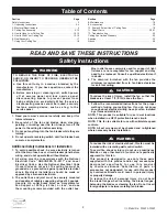
Страница 2: ...t boxes commonly used for support of light fixtures are not acceptable for fan support and may need to be replaced Consult a qualified electrician if in doubt 4 The downrod furnished with the fan prov...

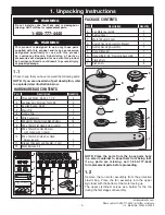
Страница 3: ...any parts are missing call 1 800 777 4440 for replacement parts before proceeding 1 2 Remove the fan motor assembly from the protective plastic bag Place the fan assembly into the upper styrofoam wit...

Страница 4: ...d for support of light fixtures are not acceptable for fan support and may need to be replaced Consult a qualified electrician if in doubt WARNING Your New Ceiling Fan will require a Grounded Electric...

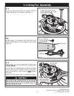
Страница 5: ...AD SCREW 2 per blade flange assembly Figure 3 3 2 Mount Flanges to Fan Blades using Three M5 x 6mm Washer Head Blade Screws supplied in parts bag Figure 2 3 3 NOTE Take care not to scratch fan housing...

Страница 6: ...Motor Hub loosen the adjacent M6 x 14mm Captive Pan Head Screw re engage and reseat the Flanges then tighten the M6 x 14mm Captive Pan Head Screw again A spare M6 x 14mm Pan Head Screw is provided in...

Страница 7: ...ighten both M4 x 10mm Serrated Pan Head Screws Figure 6 Reinstall the previously removed M4 x 10mm Serrated Pan Head Screw in the remaining Switch Housing Assembly Bracket Hole A spare M4 x 10mm Serra...

Страница 8: ...ASSEMBLY REINSTALL AND TIGHTEN M4 x 12mm FLAT HEAD SCREWS 3 Figure 9 3 9 Carefully tuck all Wires and Connectors under the Switch Housing Assembly Secure the Switch Housing Assembly by reinstalling t...

Страница 9: ...by loosening the Set Screw in the Hanger Ball until the Ball falls freely down the Downrod Figure 11 Remove the Pin from the Downrod then remove the Hanger Ball Retain the Pin and Hanger Ball for rei...

Страница 10: ...the Two Holes in the Motor Coupler Figure 13 CLEVIS PIN HAIRPIN CLIP HAIRPIN CLIP CLEVIS PIN MOTOR COUPLER Figure 14 3 14 Install the Clevis Pin and secure with the Hairpin Clip Figure 14 The Clevis P...

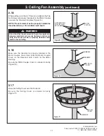
Страница 11: ...Assembly continued GROMMET DOWNROD COUPLER COVER Figure 16 3 16 Make sure the Grommet is properly installed in the Motor Coupler Cover then slide the Motor Coupler Cover on the Downrod until it rests...

Страница 12: ...OTE A loose set screw could create fan wobble It is critical that the pin in the hanger ball is properly installed and the set screw securely tightened Failure to verify that the pin and set screw are...

Страница 13: ...only used for support of light fixtures are not acceptable for fan support and may need to be replaced Consult a qualified electrician if in doubt WARNING 4 1 Securely attach the Hanger Bracket to the...

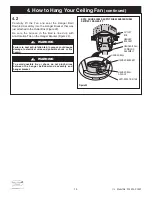
Страница 14: ...R BALL DOWNROD ASSEMBLY NOTE CEILING COVER SUPPL Y WIRES AND FAN WIRES OMITTED FOR CLARITY HANGER BRACKET HANGER BALL HANGER BALL GROOVE ANTI ROTATION TAB Figure 22 4 How to Hang Your Ceiling Fan cont...

Страница 15: ...HANGER BRACKET GREEN WIRE GROUND FROM HANGER BALL Figure 23 5 1 Connect the Green Ground Wire from the Hanger Ball and the Green Ground Wire from the Hanger Bracket to the Ground Conductor of Supply...

Страница 16: ...WHITE WIRES GREEN WIRES Figure 26 5 4 After Connections have been made turn Wires upward and carefully push Wires into the Outlet Box with the White and Green Wires on one side of the Outlet Box and p...

Страница 17: ...Service at 1 800 777 4440 if you have any questions about installation and operation of this Ceiling Fan 17 luminancebrands com Please contact 1 800 777 4440 for further assistance U L Model No CF542...

Страница 18: ...e the airflow Reverse Switch Information Season Rotation Direction Summer Counter Clockwise Winter Clockwise 7 Using Your Ceiling Fan REVERSE SWITCH SWITCH HOUSING ASSEMBLY Figure 29 7 2 Check the ope...

Страница 19: ...ning agents are not required and should be avoided to prevent damage to finish 8 Maintenance Ceiling fan performance and energy savings rely heavily on the proper installation and use of the ceiling f...

Страница 20: ...g packaging material be certain all parts have been removed HOW TO ORDER REPAIR PARTS WHEN ORDERING REPAIR PARTS ALWAYS GIVE THE FOLLOWING INFORMATION PART NUMBER NAME OF ITEM PART DESCRIPTION MODEL N...

Страница 21: ...2mm 1 14 Die cast Pendant 1 15 Pendant Coupler 1 16 Balancing Kit 1 17 Ceiling Cover 1 763921 GES 763921 GRT 763921 ORB 763921 SW 763921 VS 763921 ORB 763921 SW 18 Coupler Cover 1 764054 GES 764054 GR...

Страница 22: ...tor hub are tight 4 Wire connectors inside switch housing 4 Check to make sure wire connectors in switch rattling housing are not rattling against each other or against the interior wall of the switch...

Страница 23: ...uminance Brands Ceiling Fan Product component or Luminance Brands Ceiling Fan Product accessory caused by normal wear and tear rather than due to defects in materials or workmanship Loss or damage res...

Страница 24: ...the fan housing The date code can be found on the carton and on top of the fan housing stamped in ink on a white label You should record this data above and keep it in a safe place for future use Ques...

Страница 25: ...RT00 Grafito CF552ORB00 Bronce aceitado CF552SW00 Blanco satinado CF552VS00 Acero a ejo N meros de modelo de 52 pulgadas CF542ORB00 Bronce aceitado CF542SW00 Blanco satinado N meros de modelo de 42 pu...

Страница 26: ...ue la electricidad est desconectada en la caja de fusibles principal o el panel de cortacircuitos antes de realizar el cableado y no opere el ventilador sin paletas 2 Todo el cableado se debe realizar...

Страница 27: ...ducto est dise ado para utilizar nicamente las piezas suministradas con este producto y o los accesorios dise ados espec ficamente por Luminance Brands para utilizarse con este producto La sustituci n...

Страница 28: ...fusibles principal o el panel de cortacircuitos en este momento para retirar el accesorio de iluminaci n existente S rvase llamar a servicio al cliente al 1 800 777 4440 si tiene alguna pregunta sobr...

Страница 29: ...ilador cuando instale las paletas Instale un ensamblaje de paleta pesta a en el n cleo del motor sin apretarlo utilizando los dos tornillos de cabeza troncoc nica de tipo cautivo de M6 x 14 mm Aseg re...

Страница 30: ...ica M6 x 14 mm de repuesto por si se necesita REMOVE RETAIN ONE M4 x 10mm SERRATED PAN HEAD SCREW LOOSEN TWO M4 x 10mm SERRATED PAN HEAD SCREWS Figura 5 3 5 Retire y retenga uno de los tres tornillos...

Страница 31: ...r si se necesita SWITCH HOUSING ASSEMBLY MOTOR CONNECTOR SWITCH HOUSING ASSEMBLY CONNECTOR BLUE AND WHITE WIRES AND CONNECTORS Figura 7 3 7 Acople el conector del ensamblaje de la carcasa del interrup...

Страница 32: ...de la carcasa del interruptor reinstalando los tres tornillos de cabeza plana M4 x 12 mm restantes retirados previamente Figura 9 En la bolsa de piezas se suministra un tornillo de cabeza plana M4 x...

Страница 33: ...ensi n Retenga el pasador y la esfera de suspensi n para su reinsta laci n en el Paso 3 18 NOTA No afloje el tornillo que sujeta el cable verde de conexi n a tierra PHILLIPS HEAD SET SCREW LOOSENED HA...

Страница 34: ...4 Instale el pasador de horquilla y suj telo firmemente con el clip de horquilla Figura 14 El pasador de horquilla debe ir a trav s de los agujeros del acoplador del motor Es crucial que el pasador de...

Страница 35: ...cubierta del acoplador del motor y luego deslice dicha cubierta sobre la varilla descendente hasta que descanse sobre la carcasa del motor Aseg rese de que la cubierta del acoplador del motor est ori...

Страница 36: ...ventilador viene con cables de conexi n de color azul negro y blanco que tienen 80 pulgadas de longitud Antes de instalar el ventilador mida hacia arriba aproxima damente de 6 a 9 pulgadas por encima...

Страница 37: ...rcada con las palabras Acceptable for Fan Support of 22 7 kg 50 lbs or less Aceptable para soportar ventiladores de 22 7 kg 50 lb o menos y utilice los tornillos de montaje suministrados con la caja d...

Страница 38: ...rte de suspensi n Figura 22 4 C mo colgar su ventilador de techo continuaci n ADVERTENCIA Si no se asienta la leng eta antirrotaci n en la ranura se podr an causar da os a los cables el ctricos y posi...

Страница 39: ...para utilizarse con este producto podr a causar lesiones corporales o da os materiales GROUND CONDUCTOR SUPPLY LISTED WIRE CONNECTOR GREEN WIRE GROUND FROM HANGER BRACKET GREEN WIRE GROUND FROM HANGER...

Страница 40: ...es de conexi n de color blanco y verde en un lado de dicha caja y posicione el cable de conexi n negro negro azul en el otro lado de la caja de tomacorriente Figura 26 5 C mo cablear su ventilador de...

Страница 41: ...strados Figura 28 Apriete de manera segura los pomos estriados hasta que la cubierta del techo quede bien ajustada contra el techo y la varilla descendente no toque el agujero ubicado en la cubierta d...

Страница 42: ...e rotaci n de las paletas Verano Contrario a las agujas del reloj Invierno Agujas del reloj REVERSE SWITCH SWITCH HOUSING ASSEMBLY Figura 29 7 2 Compruebe el funcionamiento del ventilador jalando suav...

Страница 43: ...do contrario al de las agujas del reloj La circulaci n de aire producida por el ventilador crea un efecto de viento fr o que hace que usted se sienta m s fresco Seleccione una velocidad del ventilador...

Страница 44: ...irado todas las piezas C MO PEDIR PIEZAS DE REPUESTO CUANDO PIDA PIEZAS DE REPUESTO PROPORCIONE SIEMPRE LA SIGUIENTE INFORMACI N N MERO DE PIEZA NOMBRE DEL ART CULO DESCRIPCI N DE LA PIEZA N MERO DE M...

Страница 45: ...rnillo de cabeza troncoc nica serrada M4 x 10 mm 1 12 Tornillo de cabeza troncoc nica M6 x 14 mm con arandela de seguridad 1 13 Tornillo de cabeza plana M4 x 12 mm 1 14 Colgante fundido a presi n 1 15...

Страница 46: ...r an 4 Aseg rese de que los conectores de cables de la carcasa del interruptor no est n chirriando uno contra otro o contra la pared interior de la carcasa del interruptor ADVERTENCIA Aseg rese de que...

Страница 47: ...nente del Producto de Ventilador de Techo Luminance Brands o accesorio del Producto de Ventilador de Techo Luminance Brands por causa del desgaste por el uso normal en lugar de por causa de defectos d...

Страница 48: ...ficaciones ubicada encima de la carcasa del ventilador El c digo de fecha se puede encontrar en la caja de cart n y encima de la carcasa del ventilador estampado en tinta en una etiqueta blanca Usted...

Страница 49: ...T00 Graphite CF552ORB00 Bronze huil CF552SW00 Blanc satin CF552VS00 Acier classique Num ros des mod les de 52 po CF542ORB00 Bronze huil CF542SW00 Blanc satin Num ros des mod les de 42 po LISEZ ET CONS...

Страница 50: ...our viter tout risque de choc lectrique assurez vous que l lectricit est coup e au niveau de la bo te fusibles principale ou du panneau des disjoncteurs avant le c blage et ne faites pas fonctionner l...

Страница 51: ...oute substitution de pi ces ou d accessoires non d sign s comme pouvant tre utilis avec ce produit par Luminance Brands peut entra ner une blessure ou un dommage mat riel Pi ce Description Quantit A E...

Страница 52: ...it tre ancr solidement et tre capable de supporter une charge d au moins 50 livres Si votre ventilateur doit remplacer un luminaire de plafond existant coupez l lectricit au niveau de la bo te fusible...

Страница 53: ...allez les pales Attachez sans serrer excessivement un ensemble de pale bride de fixation au moyeu du moteur en s curisant les deux vis t te cylindrique bomb e captives M6 x 14 mm Assurez vous que les...

Страница 54: ...i besoin est REMOVE RETAIN ONE M4 x 10mm SERRATED PAN HEAD SCREW LOOSEN TWO M4 x 10mm SERRATED PAN HEAD SCREWS Figure 5 3 5 Retirez l une des trois vis t te cylindrique bomb e stri e M4 x 10 mm de la...

Страница 55: ...le sac de pi ces d tach es si besoin est SWITCH HOUSING ASSEMBLY MOTOR CONNECTOR SWITCH HOUSING ASSEMBLY CONNECTOR BLUE AND WHITE WIRES AND CONNECTORS Figure 7 3 7 Engagez le connecteur de l ensemble...

Страница 56: ...urisez l ensemble de bo tier de l interrupteur en r installant les trois vis t te plate M4 x 12 mm qui avaient t retir es auparavant Figure 9 Une vis t te plate M4 x 12 mm de rechange est fournie dans...

Страница 57: ...etirez la rotule de la tige de suspension Retirez l axe et la rotule de la tige de suspension en vue de leur r installation lors de l tape 3 18 REMARQUE Ne pas desserrer la vis tenant en place le fil...

Страница 58: ...Figure 14 3 14 Installez la goupille de blocage et s curisez la au moyen de la bague de retenue Figure 14 La goupille de blocage doit traverser compl tement les trous du coupleur du moteur Il est esse...

Страница 59: ...puis faites glisser le cache du coupleur du moteur sur la tige de suspension descendante jusqu ce qu il repose sur le bo tier du moteur Assurez vous que le cache du coupleur du moteur est orient corre...

Страница 60: ...ventilateur BLACK WIRE 6 TO 9 INCHES BLUE WIRE WHITE WIRE HANGER BALL 1 2 INCH 3 19 Le ventilateur est fourni avec des fils bleu noir et blanc mesurant 80 po de long Avant d installer le ventilateur m...

Страница 61: ...s de courant comportant l indication suivante Acceptable for Fan Support of 22 7 kg 50 lbs or less Acceptable pour support de ventilateur de 22 7 kg 50 lbs ou moins et utilisez les vis fournies avec l...

Страница 62: ...suspendre votre ventilateur de plafond suite AVERTISSEMENT Si la languette n est pas bien en place dans la rainure les fils lectriques pourraient tre endommag s et ceci pourrait causer un risque de ch...

Страница 63: ...VERT MISE LA TERRE PROVENANT DU SUPPORT DE SUSPENSION LISTED WIRE CONNECTOR SUPPLY WHITE NEUTRAL FAN MOTOR WHITE WIRE Figure 24 5 2 REMARQUE Si vous utilisez un luminaire Luminance Brands avec votre...

Страница 64: ...vert d un c t du coffret de prises de courant et positionnez le conducteur noir noir bleu de l autre c t du coffret de prises de courant Figure 26 AVERTISSEMENT V rifiez que tous les raccordements son...

Страница 65: ...utant que possible les boutons molet s jusqu ce que la monture de plafond soit ajust e au ras du plafond et jusqu ce que le trou dans la mon ture de plafond ne soit plus en contact avec la tige de sus...

Страница 66: ...a nette Coupez la cha nette de tirage de l interrupteur trois vitesses la longueur d sir e facultatif Connectez le pendant moul sous pression fourni l interrupteur cha nette trois vitesses en faisant...

Страница 67: ...des aiguilles d une montre Le d bit d air du ventilateur de plafond cr e un effet de refroidissement et vous procure une sensation de fra cheur S lectionnez la vitesse qui vous convient pour g n rer u...

Страница 68: ...COMMANDER DES PI CES DE RECHANGE LORSQUE VOUS COMMANDEZ DES PI CES DE RECHANGE VOUS DEVEZ TOUJOURS INDIQUER LES INFORMATIONS SUIVANTES NUM RO DE PI CE NOM DE L ARTICLE DESCRIPTION DE LA PI CE NUM RO...

Страница 69: ...10 Vis t te embase M5 x 6 mm 16 11 Vis t te cylindrique bomb e stri e M4 x 10 mm 1 12 Vis t te cylindrique bomb e M6 x 14 mm avec rondelle de blocage 1 13 Vis t te plate M4 x 12 mm 1 14 Pendentif moul...

Страница 70: ...rrupteur 4 Assurez vous que les capuchons de connexion des fils l int rieur du bo tier inf rieur ne se touchent pas ou qu ils ne touchent pas la paroi int rieure du bo tier de l interrupteur AVERTISSE...

Страница 71: ...ateur ou Produit pour un ventilateur de plafond Luminance Brands ou un accessoire d un Ventilateur ou Produit pour un ventilateur de plafond Luminance Brands caus s par l usure normale plut t que par...

Страница 72: ...bo tier du ventilateur Le code de date figure sur le carton et en haut du bo tier du ventilateur Il est estamp l encre sur une tiquette blanche Il faut enregistrer ces informations et les conserver en...

Отзывы: