LSI LASTEM E-Log – User’s manual
8
3.1.1.
Instrument power supply
Please refer to the table below for the inbound power terminal connections to the instrument and
outbound to the sensors or devices that need to be powered.
Line
Model
Connection
Terminal
Inbound
ELO105
ELO305
ELO310
ELO505
ELO515
0 Vdc battery
64
+ 12 Vdc battery
65
GND
66
Outbound
All
+ Vdc fixed to power sensors/external devices
31
0 Vdc
32
+ Vdc actuated to power sensors/external devices
33
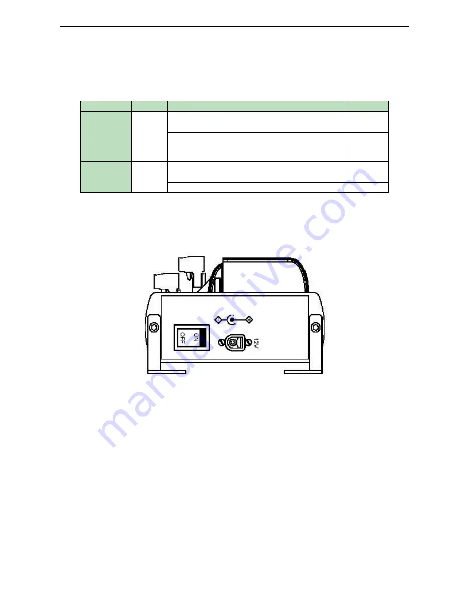
All models may also be powered by an external power supply by means of the connector located on
the right-hand side panel; in this case the positive pole is the one inside the connector. In any case
pay attention not to invert the power polarity (although the instrument is protected from wrong
procedure).
Picture 3
Whenever available, connect the ground wire (GND) to terminal 66. If the round wire (GND) isn’t
available, you make sure to connect terminals 60 and 61 (short circuit). This measure will improve
the immunity from electromagnetic noises and the protection from induced and conduced electrical
discharges.
In order to use E-Log datalogger with low energetic consumption modality see §5.7
WARNING:
in case the 31 and 32 terminals feed outside equipments, they must be equipped with
power fail circuit against short circuits or absorbed currents above 1A.
Содержание E-Log
Страница 1: ...Cod INSTUM_00351_en E Log User s manual Updated on 09 18 2017...
Страница 15: ...LSI LASTEM E Log User s manual 15...
Страница 60: ...LSI LASTEM E Log User s manual 60 6 6 Mask of terminal board...
Страница 61: ...LSI LASTEM E Log User s manual 61 6 7 Connection cables...
Страница 62: ...LSI LASTEM E Log User s manual 62 6 8 Declaration of Conformity...


