


REG. CODE
1-5302-509
MODEL N°
50778
DATE OF ISSUE
10.06.99
REVISION
00
DATE
10.06.99
ENDORSED
COMPILER TECO/ATI
32
DISASSEMBLY/REASSEMBLY
VIII
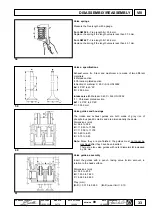
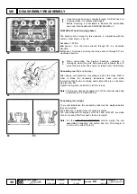
Intake, exhaust cam height
LGW 523
A1 = 1st cylinder intake
S1 = 1st cylinder exhaust
A2 = 2nd cylinder intake
S2 = 2nd cylinder exhaust
H = 30.78 to 30.718 mm (intake and exhaust cam height)
LGW 627
A1 = 1st cylinder intake
S1 = 1st cylinder exhaust
A2 = 2nd cylinder intake
S2 = 2nd cylinder exhaust
H = 30.64 to 30.578 mm (intake and exhaust cam height)
Do not demount or remount while hot as this could lead to
deformations.
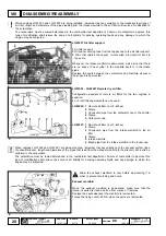
CYLINDER HEAD, removal
If deformation exceeding 0.10 mm is gauged on the cylinder head
surface, level off by grinding, removing 0.20 mm at most. Consult
fig. 82 when tightening the head.
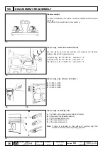
Valves
To remove the valves, first take out the cotters. Place a shim under
the valve mushroom, strongly press on the upper spring plate as
shown in the figure.
Components:
1 Valve stem
2 Oil retainer seal
3 Lower spring ring
4 Spring
5 Upper spring ring
6 Cotters
Oil retainer seal in valve guide, removal
To prevent seal 1 from being deformed when the valve guide is
mounted, fit it into tool 2 (serial N° 7107-1460-047 on page 92) and
proceed as shown in the figure, making sure that the seal 1 is fully
inserted.
56
57
52
53
54
55


