


REG. CODE
1-5302-509
MODEL N°
50778
DATE OF ISSUE
10.06.99
REVISION
00
DATE
10.06.99
ENDORSED
COMPILER TECO/ATI
28
37
39
38
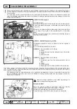
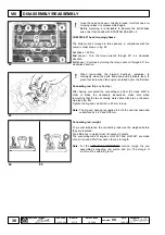
LGW 627 rocker cap
Many of the more important engine components are on the cylinder
head.
The rocker cover houses part of the camshaft lubrication duct, that
of the rockers and part of the engine bleeding system.
External parts of the rocker cover:
1 Screw to fix the rocker cover to the cylinder head
2 Pressure switch (the only point where the engine oil pressure can
be gauged)
3 Oil fill plug
Tighten the fixing bolts to a 9 Nm torque when remounting the cover.
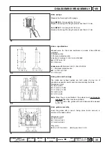
Rocker cover and recirculated oil vapour bleeding system for
engine LGW 627
Internal parts of the rocker cover:
1 Camshaft and rocker rod lubrication ducts
2 Oil vapour cooling labyrinth
3 Vent vacuum valve
4 Space allowing oil vapour to pass from the cylinder head to the
rocker cover
5 Outlet for vapour re-converted into oil by cooling in the labyrinth
with consequent return to the sump
6 Outlet to vent oil vapours from the duct to the intake manifold
7 Hole to drain oil from the cylinder head
8 Oil return from bleed to sump (see description in point 5)
9 Seal between rocker cover and cylinder head
The rocker cover seal ensures that the rocker pivot camshaft
lubrication circuit is tight. It is therefore advisable to replace it
whenever it is demounted and to remount it with particular care.
Damage or breakage of the seal could lead to a pressure drop in the
lubrication circuit.
Torque the fixing screws to 9 Nm when remounting the cover.
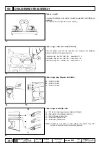
By physical principle, oil vapours reach the cylinder head from the
top part of the engine through hole 4 fig. 38.
The moment in which the vapours approach the cover inlet, they are
attracted by the vacuum created in the intake manifold (with the aid
of valve 3 of fig. 38) with which the cover is in communication (from
6 to intake manifold see fig. 39 ).
To prevent excessive amounts of oil from reaching the manifold
along with the vapour in certain extreme conditions (e.g. lack of filter
maintenance, wear on the cylinders, etc.), the venting system has
been designed to decant the drops of oil during its passage through
labyrinth 2 of fig. 38 and to allow them to return to the sump along
the route (5 --> 8 of fig. 39).
Vapour that is not re-converted into oil enters intake manifold 6 of
fig. 39.
DISASSEMBLY/REASSEMBLY
VIII


