background image

6


Placing the heating system in operation

Logano G334X – 6 720 811 237 (2014/05)

21

Carrying out leak test

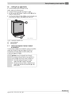
5. Open the gas shutoff valve.

6. Check the gas supply line to the gas valve for leaks with soap solution. 

If no leaks are found, continue with step 8.

7. If leaks are detected, close the gas shutoff valve, seal the leaks, and 

repeat step 6.

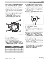
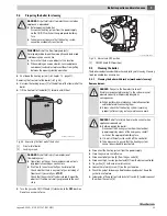
8. Close the gas shutoff valve. Remove the screw plug from the gas 

supply pressure test point [2] on the gas valve in order to measure 
the gas supply pressure. Install pressure test port and attach a 
pressure gauge.

9. To measure the orifice pressure, remove the screw plug from the 

orifice pressure test point [3] on the gas valve. Install pressure test 
port and attach a pressure gauge.

Fig. 27 Gas valve 

[1]

ON/OFF knob (ON position) 

[2]

Screw plug for gas supply pressure test port

[3]

Screw plug for orifice pressure test port

10. Open the gas shutoff valve and measure the gas supply pressure to 

the boiler. The supply pressure for natural gas must be between 
7"...10.5" W.C. (17.4...26.2 mbar) and between 11"...13" W.C. for 
propane gas (27.4...32.4 mbar). If the connection pressure is not in 
this range with natural gas, contact your customer service technician 
or gas utility company. Close the gas shutoff valve.

11. Follow the startup instructions in Section 6.3.

6.3

Start-up instructions 

For your own safety, read the following information carefully before 
commissioning:

NOTICE: 

Risk of system damage due to short-circuits!

▶ Cover any hazardous locations prior to locating the 

leaks.

▶ Do not spray leak detector onto conduits, plugs or 

electrical connection cables or allow it to drip onto 
them.

DANGER: 

Risk of fatal injury from failure to observe the 

commissioning instructions and subsequent incorrect 
operation!
Risk of fire and explosion from failure to observe the 
startup instructions.

▶ Read the startup instructions carefully before 

commissioning.

DANGER: 

Risk of fatal injury from gas explosion!

If you smell gas there is a danger of explosion.

▶ Close the gas shutoff valve.
▶ Open windows and doors.
▶ Do not operate any electrical switches or telephones.
▶ Do not use any sockets.
▶ Extinguish all open flames. No smoking. Do not use 

lighters.

▶ Warn all occupants of the building that they need to 

leave the building.

▶ Do not ring doorbells.

From outside the building:

 Notify the police and fire 

department.

From outside the building:

 Call the gas supply 

company and a trained and certified installer or 
service company.

NOTICE: 

System damage!

This appliance is fitted with an ignition module that 
automatically starts the pilot burner.

▶  Do not attempt to light the ignition flame manually.

NOTICE: 

System damage!

The following test must also be conducted at floor level, 
because some gas types are heavier than air and may 
accumulate at floor level.

▶  Check for odor of gas around the heating system.

DANGER: 

Risk of system damage from fire or explosion!

Any attempt to use force or to repair the gas shutoff 
valve may cause a fire or explosion.

▶ Operate the ON/OFF knob on the gas valve by hand 

only. 

▶ Do not use any tools. 
▶ If the ON/OFF knob on the gas valve cannot be 

operated by hand: Do not repair it. 

▶ Contact a qualified and certified service company. 

NOTICE: 

Risk of system damage from corrosion!

▶ Do not use the appliance if any part of it has been 

under water.

▶  Contact a qualified and certified service company.

Содержание G334X

Страница 1: ...in this installation and mainte nance manual exactly If you require assistance or further information contact a qualified contractor a suitable service provider or the gas supply company WARNING These instructions are part of the technical documents that must be handed over to the owner operator of the heating system Discuss the content of this manual with the owner operator of the heating system ...

Страница 2: ...lling front wall of boiler 17 5 10 Connecting the flue connector 17 5 10 1 Check openings for combustion air supply and venting 17 5 10 2 Requirements for connection to chimneys or flue gas systems 18 5 10 3 Installing the flue pipe 19 5 10 4 Connecting the flue connector 19 5 10 5 Installing a vent damper optionally available 19 5 10 6 Electrically connecting the vent damper 20 6 Placing the heat...

Страница 3: ...iler is not be fitted with a barometric damper or a thermally controlled vent damper downstream of the flue connector Do not tamper with remove or attempt to repair the flue gas shutoff switch When replacing the flue gas shutoffswitch install the new part inthe original location Afluegasshutoffswitchtrippingmorethanonceindicatesaproblem with the flue gas system or chimney which must be repaired im...

Страница 4: ...the owner operator that they must never carry out any modifications or repairs 2 Product Description This installation and maintenance manual contains important information for the safe and correct installation initial commissioning and maintenance of this boiler The Logano G334X floor standing gas boiler is generally referred to below as a boiler The installation and maintenance manual is provide...

Страница 5: ...ndfill Notice regarding environmental protection and disposal Chapter 8 page 28 2 6 Product Description The boiler is a gas floor standing boiler employing gas combustion The boiler consists of the following main components Fig 1 Burner controller and aquastat Logamatic 2107 control optional control Boiler casing and front wall Boiler block with thermal insulation Burners Theburnercontroller theaq...

Страница 6: ... 2 3 25 3 5 2 3 5 40 2 3 6 720 810 547 02 1T 3 4 2 1 Boiler size Unit 73 92 116 132 Ignition heat load MBTU hr 301 378 476 541 kW 88 2 110 7 139 4 158 4 Nominal output MBTU hr 249 314 396 450 kW 73 92 116 131 8 Dimension A inches 34 5 41 7 48 8 55 9 mm 876 1059 1240 1420 Dimension B VENT inches 8 9 10 10 mm 203 229 254 254 Minimum capacity of the safety relief valve lb hr 249 314 396 450 kg h 113 ...

Страница 7: ...65 4 4 10 9 116 7 3 90 3 85 4 1 10 4 132 8 3 90 3 85 4 2 10 7 Table 5 Main gas orifice identification and rated orifice pressure for natural gas Boiler size Number of injectors Main gas orifice identification for the altitude feet Rated orifice pressure for liquid propane 0 8500 ft1 8501 12000 ft1 1 Use conversion components only as directed by the technical documentation In W C mbar 73 5 2 35 2 3...

Страница 8: ...6 inches NOTICE Risk of system damage from impact shocks Fragile components could be damaged Observe the transport instructionsonthe packaging NOTICE System damage due to improper transport Protect sheet metal parts flue gas pipe burner and control unit during transport Do not use these components to lift the boiler Dispose of the packaging material in an environmentally prudent fashion WARNING Ri...

Страница 9: ...he included parts Route the gas connection towards the left If the gas connection needs to be on the left Loosen the unions on the gas supply pipe completely Reattach and seal the gas supply pipe after rotating it 180 Carry out leak test 5 2 Installing the flue gas collector or the collection manifold Fasten the flue gas collector to the draft diverter with the eight retaining screws Fig 7 Install...

Страница 10: ...e panels with 2 self tapping screws Fig 9 Side panels and front boiler jacket 1 Rear tab 2 Side hook 3 Side panel screws 5 4 Connecting the heating system This section explains how the boiler is connected to the heating system 5 4 1 Safety instructions Fig 10 Low water indicator A Heating system with low water indicator B Heating system without low water indicator 1 Boiler 2 Panel radiator 6 720 8...

Страница 11: ...theheatingcoilsof a hot air heating system these may be exposed to the circulation of cool air In this case the boiler piping must be equipped with a flow control valve or some other automatic system for preventing the boiler water from circulating by gravity during the cooling cycle NOTICE Risk of system damage due to leaking connections Connect pipes without stress to the boiler connections DANG...

Страница 12: ...rew the screws from the top cover 1 Remove the top cover from the controller Secure the control panel with self tapping screws 2 Fig 14 Removing the top cover 1 Top cover screws 2 Self tapping screws Installing the boiler water sensor Route boiler water capillary package wiring under the front boiler cover to the measuring point sensor well Remove dummy from the sensor well Insert the boiler water...

Страница 13: ...wiring from above into the slot of the clip frame the lever bar must point upwards step 1 Slide the cable ties downwards step 2 Push against the clips step 3 Flip the lever up step 4 Fig 16 Secure wiring with wiring clip Installing jacket panels Swivel display unit to the desired position Fig 17 Swivel display unit Position terminal cover and screw to control Fig 18 Positioning the terminal cover ...

Страница 14: ...to contamination If the boiler is installed and not being used Protect the boiler connections to prevent accumulation of dirt Notethefollowingpointsforestablishingthefuelsupply Work on gas components may be carried out only by qualified and authorized personnel Observe the local regulations or else the requirements the National Fuel Gas Code ANSI Z 223 1 when connecting the gas supply In Canada th...

Страница 15: ...120 250 380 710 1130 Table 8 Gas pipe supply volume Iron pipe nominal diameter in inches Equivalent lengths for pipe fittings in feet 1 foot 0 3 m Pipe fitting type 90 elbow T piece Shutoff valve Gas shutoff 1 3 5 0 6 1 60 1 4 6 0 8 2 15 1 5 7 1 0 2 50 2 7 10 1 3 3 00 2 8 12 1 6 3 50 Table 9 Equivalent lengths for pipe fittings DANGER Risk of explosion Leakage from the gas pipes and gas connection...

Страница 16: ...mage due to excess pressure when testing for leaks Pressure control and safety equipment may be damaged by excessive pressure When you carry out a leak test make sure that no pressure control or safety device that cannot be isolated from the boiler s water chamber is installed WARNING Health risk from contaminated drinking water Always observe the regulations and standards applicable in your juris...

Страница 17: ...ide the connected rooms Make sure that the cross sectionalareaof eachventisatleast100 squareinches 0 06 m2 One of the vents must be no more than 12 inches 300 mm from the ceiling and the other no more than 12 inches 300 mm from the floor of the boiler room measured from the outer edge of the vent opening The smallest dimension of all air intake and outlet openings must be not less than 3 inches 80...

Страница 18: ...mendations for flue connection and chimney liners A flue pipe of single walled sheet metal is required for flue connections for type II models An adequate chimney height in compliance with the tables of the National Fuel Gas Code ANSI Z 223 1 is required Disconnecting a boiler from a common flue gas system If an existing boiler is disconnected from a common flue gas system the flue gas system is n...

Страница 19: ...additional components Connectventpipetothechimneywiththeshortestpossiblelengthof vent pipe 5 10 5 Installing a vent damper optionally available Theventdampersuppliedwiththeboilermustbeusedsolelyforventing the boiler The position of the vent damper position blade must be visible The flue gas collector must be at least 6 inches 155 mm from all flammable components The vent damper must be readily acc...

Страница 20: ...ws 2 at the bottom of the front wall of the boiler 1 lift front wall of boiler tilt it forward and remove it Fig 26 Removing front panel of boiler 1 Front wall of boiler 2 Locking screws DANGER Danger to life from electric shock Only qualified electricians are permitted to carry out electrical work Beforeopeningtheappliance disconnectitfromthe power supply by means of the emergency shutoff switch ...

Страница 21: ...cal connection cables or allow it to drip onto them DANGER Risk of fatal injury from failure to observe the commissioning instructions and subsequent incorrect operation Risk of fire and explosion from failure to observe the startup instructions Read the startup instructions carefully before commissioning DANGER Risk of fatal injury from gas explosion If you smell gas there is a danger of explosio...

Страница 22: ...the factory installed aquastat A Logamatic 2107 controller can be installed in addition to the factory installed aquastat The ON OFF switch on the controller switches the heating system ON The burner starts operating if heat is required observe controller service manual 5 Check the controller to make sure that heat is required Use the operating mode selector switch to select the Manual operation o...

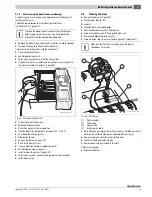
Страница 23: ... the adjustment screw clockwise to increase the orifice pressure Turn the adjustment screw counterclockwise to decrease the pressure 15 Record the value set in the commissioning report Chapter 6 8 page 26 Screw the safety screw for adjusting the orifice pressure 3 back into the gas valve 16 Observe ignition flame through the inspection hole in the burner cover Fig 30 page 22 17 The flame must surr...

Страница 24: ...ply and set the thermostat to the lowest setting 29 Removepressuretestportandpressuregaugeformeasuringthegas supply pressure and orifice pressure from the gas valve Close the openings with the screw plugs 2 and 3 again 30 Repeat steps 1 to 11 depending on the controller used and step 20 Thus the heating system is started up again Check the screw plugs 2 and 3 for leaks with soap solution If no lea...

Страница 25: ...1 Front wall of boiler 2 Locking screws 6 7 Inform owner operator hand over technical documentation Familiarize the owner operator with the entire heating system and the operating instructions for the boiler Hand over the technical documentation to the owner operator and then both sign the commissioning report on this page NOTICE Risk of system damage due to freezing The heating system may freeze ...

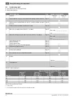
Страница 26: ... Meas value _____________________________ Unit ________________________________ 7 Leak test during operation Check ignition flame Check main burner flame Check that flue gas system is functioning properly Page 21 Page 23 Page 23 Page 18 8 Check maximum aquastat setting Page 24 9 Installing front wall of boiler Page 17 10 Inform operator hand over technical documentation Page 25 11 Installer Signat...

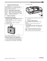
Страница 27: ...y Fig 37 Shutting down heating system with Logamatic 2107 control 1 ON OFF switch 7 2 Emergency shutdown procedure Inform the owner operator of the procedure to follow in case of emergency Never put yourself at risk Your own safety is paramount Shut off gas supply Shut off the heating system by means of the emergency shutoff switch located outside the installation room or the appropriate building ...

Страница 28: ...tems must be serviced annually for the following reasons To maintain high efficiency Economical operation low fuel consumption To achieve a high level of operational safety To maintain the cleanest combustion To ensure reliable operation and a Long service life Maintenance work must be carried out only by a trained and certified installer or service company When replacing components only Bosch app...

Страница 29: ...y via the ON OFF switch or the appropriate building fuse Take measures to ensure that the heating system cannot be accidentally reactivated WARNING Risk of fire from foreign objects Foreignobjectsbetweenthemainorificeandburnerrod inlet opening can cause a fire Ensure that there are no objects at this location When working on an open boiler Secure appliance componentsandcablestopreventthemfromgetti...

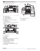
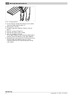
Страница 30: ...he spacers 2 remain on the studs Fig 41 Removing the burner 1 Retaining nuts 2 Studs with spacers Cleaning the boiler Remove the boiler casing and thermal insulation check for damage Unscrew cleaning cover from the draft diverter Use cleaning brushes to brush out hot gas flues To prevent entry of metal dust into the control unit Cover controller with foil Clean combustion chamber and bottom panel ...

Страница 31: ... gas flues Clean combustion chamber and bottom panel Ventilate boiler room well again Install or clean the burner page 31 Screw cleaning cover into place and replace thermal insulation Install boiler casing 9 6 Cleaning of burner Remove the burner page 29 Check burner rods for dirt If necessary Clean burner as described below Unscrew pilot burner unit 1 from burner Disconnect pilot gas line 3 from...

Страница 32: ... Chapter 6 starting on page 20 Check the functioning of the aquastat Check low water indicator if one is installed Check area around boiler for hazards The area around the boiler must be free from flammable substances gasoline or any other flammable or corrosive vapors and liquids Complete the maintenance log to confirm that all maintenance work has been carried out Chapter 9 8 page 35 Sign the ma...

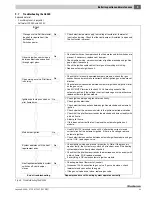
Страница 33: ...urns evenly with a bluish flame If OK replace electrode If everything is OK replace automatic ignition module No Heat requirement ended system switches off vent damper closes End of troubleshooting Repeat procedure until heating system operates correctly On models with vent damper check that it operates and lmit switches are present If necessary replace vent damper Check ignition wiring ceramic in...

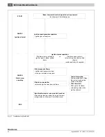
Страница 34: ... monitors pilot flame Specified thermostat value control reached Main and ignition gas valves close gas burners extinguished vent damper if installed closes Ignition burner operation Pilot flame burns automatic ignition signals steady ignition flame or Pilot flame does not burn automatic ignition starts ignition attempt switches off after 90 seconds END PHASE 1 Ignition attempt PHASE 2 Main burner...

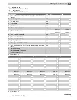
Страница 35: ...Page 21 ___________ inches W C ___________ inches W C 8 Check for leaks during operation Page 21 9 Check the pilot burner flame Page 23 10 Check the main burner flame Page 24 11 Checking vent damper Page 19 12 Check high temperature limit controller Page 24 13 Check the area around the boiler for flammable materials gasoline or corrosive liquids Page 3 14 Confirm maintenance Confirmation of proper...

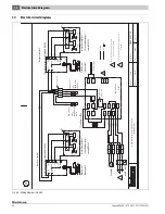
Страница 36: ...ntermittent pilot control module S8600H PV Plug Plug 63028623 6646 Intermittent pilot Wiring diagram gas boiler G334X USA CDN switch on off 1 H N Page 1 2 US C1 G L2X B2 C L1 C2 L2 L1X B1 R R S1 S2 C R W Boiler Sensor 4 L1 L1 N N L1 L1 N N M Transformer 40VA X2 X1 24V 120V green black blue black blue white black yellow blue black orange orange black green 120 VAC 24V 18 WIRE 24V 24V MV MV PV PV GN...

Страница 37: ...e Spark Burner To Pilot switch On off Circulator red white blue green 2 4 3 Transformer L1X R C L2X M X2 N X2 L1 X1 N K2 L1 C2 C1 T Stat TV R T W K1 1 B1 24VGND 24V MV PV MV PV GND S8600H MV GND MV PV PV Pilot Main Gas valve Spark Burner To Pilot red white blue green shutoff means safety Flame roll out left site right site Wiring diagram Edition Reviewed Drwg no GAW 029 USA 2004 03 63028623 6646 I...

Страница 38: ...10 Logano G334X 6 720 811 237 2014 05 38 Notes ...

Страница 39: ...10 Logano G334X 6 720 811 237 2014 05 39 Notes ...

Страница 40: ......

Отзывы: