27
Fertilizer Spreader OM
Maintenance
Removing the Rear End
The rear end can be removed if repairs, replacement, or
reconditioning should ever be needed.
To disassemble, remove the conveyor chain, rear spindle
drive belt, bumper, and both spinners. Locate splice pin
in conveyor chain. Remove the bolts securing the rear
end.
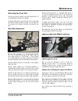
Rear Belt Alignment
1
2
6
7
5
A
D
F
E
B
C
3
4
Section of belt marked as “A” in the photo above should
be in line. If adjustment needs to be made, align the
two spinner sheaves (1 - left spinner; 2 - right spinner)
to the same height and as high as possible, maintaining
clearance between belt and underside of idler bracket.
Section of belt marked as “B” should be in line or slightly
lower than idler.
Section of belt marked as “C” should be parallel to a
straight edge (3) placed along the face of the line shaft
sheave (4). Move the sheave on the line shaft to adjust.
Section of belt marked as “D” should run parallel to the
face of the idler sheave (5). If an adjustment is needed,
bend the idler sheave bracket to reach proper alignment.
Section of belt marked as “E” must have a 90° clockwise
twist between sections “D” and “E” to run same surface
of belt through the grooves of the line shaft and idler
pulleys.
Section of belt marked as “F” should be tightened so 1
in. (2.54 cm) deflection occurs with 20 lbs. of pressure
applied at mid point between the line shaft sheave and
the idler sheave. Tension should be rechecked after 2
hours of field use.
To tighten belt tension, loosen inner nut on the belt
tension bolt (6) and tighten the outer nut (7) until proper
belt tension is achieved. To loosen the belt tension,
reverse this procedure.
Belt guide stop must be tight against mounting bracket
to assure proper protection by guide.
Optional 540/1000 RPM Dual Drive
Drive Belt
Adjusting Belt Tension
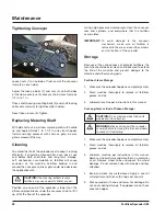
Belt (1) should be tightened so .094 in. (2.38 mm)
deflection occurs with 11 lb. of pressure applied at
midpoint between pulleys. Inspect for proper tension
and retighten if necessary after each load.
Alignment of HTD (High Torque Drive) Belts
Alignment is critical in use of HTD drives. Shafts at each
end of belt must be absolutely parallel to one another so
the belt engages evenly across the sheaves.
Poor assembly and alignment will damage a HTD belt.
Never pry or force a belt onto a sheave. Belts must be
slid onto sheaves by either removing a flange or moving
sheaves closer together.
Use Loftness part number N41602 when replacing a
drive belt.
Содержание FS 800
Страница 2: ......
Страница 4: ......
Страница 8: ......
Страница 28: ...20 Fertilizer Spreader OM ...
Страница 38: ...30 Fertilizer Spreader OM ...
Страница 39: ...31 Fertilizer Spreader OM PARTS IDENTIFICATION AND HYDRAULIC SCHEMATICS Parts Identification ...
Страница 63: ...55 Fertilizer Spreader OM Appendix Torque Specifications Inches Hardware and Lock Nuts ...
Страница 64: ...56 Fertilizer Spreader OM Appendix Torque Specifications Cont d Metric Hardware and Lock Nuts ...
Страница 65: ......


