20
5
Boiler side piping
Installation & Operation Manual
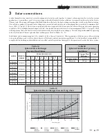
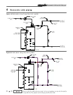
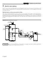
Figures 5-1 and 5-2 show typical boiler piping for single and multi-tank situations. A pressure relief valve must be installed on each
boiler and each tank, as regulations require. The tank pressure relief valve should be sized to meet the working pressure of the tank
according to local codes.
Multiple tank connections (boiler side)
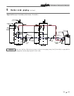
Boiler piping works most efficiently when it is done in the reverse-return application. This method uses more piping than direct
return systems, but the pressure drop and boiler flow are more balanced throughout each tank. To ensure even charging and
discharging of each tank, it is recommended that only tanks of the same size are placed in the same manifold. It is recommended
that each tank be equipped with its own isolation valves, unions and drains so that one tank may be removed from the system, if
necessary.
PRESSURE
RELIEF VALVE
TEMPERATURE
GAUGE
BACKUP
HEAT SOURCE
SENSOR
FILL
VALVE
AIR
SEPARATOR
Y-STRAINER
(TYPICAL)
CHECK
VALVE
BOILER
CIRCULATOR
PRESSURE
RELIEF
VALVE
T&P
GAUGE
DRAIN
BACKUP
HEAT SOURCE
IMG00086
Please note that these illustrations are meant to show system piping concept only, the installer is responsible for
all equipment and detailing required by local codes.
NOTICE
Figure 5-1 Backup Heat Source Connection

