Installation & Operation Manual
75
Inspect and clean the heat exchanger
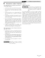
1. While burners are removed, check the heat exchanger
surface for sooting. If present, heat exchanger must be
cleaned and problem corrected. Proceed as follows.
2. Remove gas manifold(s)/orifice assemblies as described
in steps 1 through 5 in Burner Removal and Cleaning,
page
74.
3. Disconnect wiring from the hot surface igniter and
hose from the burner pressure tap.
4. Remove inner jacket panel mounting screws and slide
door assembly out toward front of the unit. Use
caution to prevent damage to the refractory and hot
surface
igniter.
5.
Check “V” baffles and frame runners along front
and back edges of heat exchanger. Remove and clean if
necessary.
6. Remove soot from heat exchanger with a stiff bristle
brush. Use a vacuum to remove loose soot from
surfaces and inner chamber.
7. The heat exchanger can be removed by sliding towards
the front of the unit. Once the heat exchanger is
removed from the unit, a garden hose can be used
to wash the tubes to ensure that all soot is removed
from the heat exchanger surfaces. Note: Do not wet the
unit’s
refractory.
8. Ensure that all burner ports are cleaned to remove any
soot. See Burner Removal and Cleaning, page 74.
9. Carefully reinstall the heat exchanger, “V” baffles, and
frame runners if removed from the unit. Note: Make
sure frame runners seal securely where they contact the
front and rear compartment refractory.
10. Carefully reinstall inner jacket panels, burners,
manifolds, wires and hoses. Use new gasket material to
ensure a proper air seal.
11. Reassemble all gas and water piping. Test for gas leaks.
Upon completion of any testing on the gas
system, leak test all gas connections with a
soap and water solution while main burners
are operating. Do not spray soap and water
solution on the SMART SYSTEM control
module housing. The use of an excessive
amount of soap and water solution can
damage the control. Immediately repair
any leak found in the gas train or related
components. Do not operate an appliance
with a leak in the gas train, valves, or related
piping.
NOTICE
HEAT
EXCHANGER
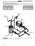
Figure 9-3_Location of the Heat Exchanger Inside
Jacket
Review with owner
1. Review the Copper-fin II User’s Information Manual with
the owner.
2. Emphasize the need to perform the maintenance schedule
specified in the Copper-fin II User’s Information Manual
(and in this manual as well).
3. Remind the owner of the need to call a licensed contractor
should the appliance or system exhibit any unusual behavior.
4. Remind the owner to follow the proper shutdown procedure
and to schedule an annual start-up at the beginning of the
next heating season.
Oiled bearing circulators
Inspect the pump every six (6) months and oil as necessary. Use
SAE 30 non-detergent oil or lubricant specified by the pump
manufacturer.
9
Maintenance
(continued)
12. Reassemble outer jacket panels.
13. Cycle unit and check for proper operation.


