BEFORE
YOU
BEGIN
12
INTRODUCTION
IMPORT
ANT
PRECAUTIONS
ASSEMBL
Y
BEFORE
YOU
BEGIN
TREADMILL
OPERA
TION
LIMITED
W
ARRANTY
TROUBLESHOOTING
&
MAINTENANCE
CONDITIONING
GUIDELINES
BEFORE YOU
BEGIN
ASSEMBL
Y
13
INTRODUCTION
IMPORT
ANT
PRECAUTIONS
TREADMILL OPERA
TION
CONDITIONING GUIDELINES
TROUBLESHOOTING &
MAINTENANCE
LIMITED WARRANTY
ASSEMBLY
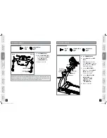
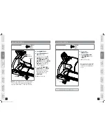
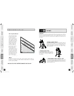
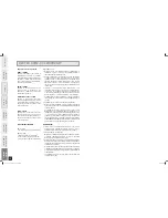
STEP 5
HANDLEBAR
CONSOLE
HANDLEBAR CAP
SCREWS (F)
SCREWS (F)
MAIN FRAME
*NOTE:
The right handlebar side cap is marked with
“R” on the side of the cap and the left handlebar
side cap is marked with “L” on the side of the cap.
ASSEMBLY COMPLETE!
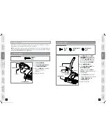
ASSEMBLY
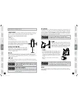
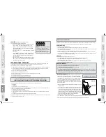
STEP 6
SCREWS (F)
HANDLEBAR COVER
HANDLEBAR
A
Open
HARDWARE BAG 5
.
B
Align
LEFT HANDLEBAR
with
CONSOLE
as shown.
C
To attach the top of the
LEFT
HANDLEBAR
to the
CONSOLE
,
slide
HANDLEBAR CAP
through
HANDLEBAR
and place 2
SCREWS
(F)
into the side of the
LEFT
HANDLEBAR
and tighten all
screws completely.
D
To attach
LEFT HANDLEBAR
to
MAIN FRAME
, place 2
SCREWS
(F)
through the side and 2
through the top of the frame
and lightly tighten to the
MAIN FRAME.
E
Repeat on other side.
SCREW (F)
15 mm
Qty: 18
HARDWARE BAG 5 CONTENTS :
SCREW (F)
15 mm
Qty: 18
HARDWARE BAG 5 CONTENTS :
A
Continue using
HARDWARE BAG 5
.
B
Attach
HANDLEBAR COVER
to
LEFT HANDLEBAR
using 3
SCREWS (E)
.
C
Repeat on other side.
Before the first use, lubricate the
treadmill deck by following the
instructions in the Maintenance
section.
LS16.9T_owners_manual_Rev.1.1.indd 12-13
9/9/09 10:57 AM


