Installation Guide Linear Motors
ENG
Page 8 / 32
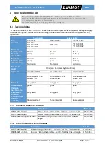
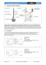
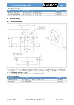
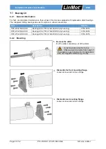
P10-70-SSC / P10-70-SSC-D02
NTI AG / LinMot
Insert the slider in the defined direction (see
Assembly step 5.).
Large magnetic attraction forces
(Observe warning notice from page 5)!
If necessary, cover obvious iron constructions
with non-magnetic material (e.g. wood).
Slider back end:
M8 thread
Slider front end:
M10 cut-in
Checking the installed direction of slider
After the installation, the front end of the slider
with M 10 thread and cut-in is located at the
opposite side of the stator from the cable exit.
Slider back end should not be used for
load mounting!
Mounting the stator
The motor is levelled and fixed to the ground using the holes in the flange foot.
The hole pattern is shown in section 9.1 "Stator Dimensions".
Mounting the payload to the slider
The load is mounted as a fixed bearing using spherical washers and conical seats (see the section 6.3).
•
To avoid shear force on slider and wear on stator, the payload has to be beared by a
linear guide.
•
Slider back end (M8 internal thread) should not be used for load mounting.


