background image

Impinger II – Installation & Operation Manual 

2

TABLE OF CONTENTS 


IMPORTANT WARNING AND SAFETY INFORMATION ............................................................................................ 3 
PURCHASER’S RESPONSIBILITY ............................................................................................................................. 4 
MODEL NUMBER KEY ................................................................................................................................................ 5 
UTILITY SPECIFICATIONS REQUIRED – ELECTRIC................................................................................................ 6 
UTILITY SPECIFICATIONS REQUIRED – GAS .......................................................................................................... 6 
EXTERIOR DIMENSIONS ............................................................................................................................................ 7 
GENERAL INFORMATION ........................................................................................................................................... 8 

IF THERE IS APPARENT DAMAGE: ....................................................................................................................... 8 
PACKING AND WEIGHTS ........................................................................................................................................ 8 

UNCRATING ................................................................................................................................................................. 8 
ASSEMBLY INSTRUCTION ......................................................................................................................................... 8 
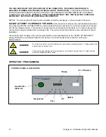
STACKING INSTRUCTIONS ........................................................................................................................................ 9 
SPACING .................................................................................................................................................................... 11 
VENTILATION............................................................................................................................................................. 11 

VENTILATION GUIDELINES .................................................................................................................................. 11 
VENTILATION RECOMMENDATIONS .................................................................................................................. 12 
VENTILATION SYSTEM VERIFICATION ............................................................................................................... 12 

UTILITY SERVICE LAYOUT ...................................................................................................................................... 13 
INSTALLATION CODES AND GUIDELINES ............................................................................................................. 13 
OPERATION / PROGRAMMING ................................................................................................................................ 14 

INTRODUCTION:  START-UP AND SHUT DOWN ................................................................................................ 15 
FRONT PANEL LAYOUT ........................................................................................................................................ 15 
TEMPERATURE SETPOINTS ................................................................................................................................ 15 
TIME SETPOINTS .................................................................................................................................................. 15 
JUMPING BETWEEN MENUS ............................................................................................................................... 15 

DIAGNOSTIC MESSAGES ........................................................................................................................................ 15 

PROBE FAIL ........................................................................................................................................................... 15 
BELT JAM ............................................................................................................................................................... 15 

FUNCTIONS ............................................................................................................................................................... 15 

REVERSING SWITCH ............................................................................................................................................ 15 
THERMAL CUT-OUT SWITCH ............................................................................................................................... 15 

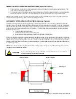
MANUAL QUEST OPERATING INSTRUCTIONS (Optional Feature) ....................................................................... 16 
AUTOQUEST OPERATING INSTRUCTIONS (Optional Feature) ............................................................................. 16 
RESTRAINT REQUIREMENT – Gas Oven(s) on Casters ......................................................................................... 17 
CONVEYOR REMOVAL ............................................................................................................................................. 18 
FINGER REMOVAL .................................................................................................................................................... 18 
OPERATOR MAINTENANCE ..................................................................................................................................... 19 
CLEANING INSTRUCTIONS ...................................................................................................................................... 19 
PREVENTIVE MAINTENANCE .................................................................................................................................. 20 
HOW TO OBTAIN SERVICE ...................................................................................................................................... 20 
APPENDIX A – LABEL DEFINITIONS ....................................................................................................................... 21 
LIMITED WARRANTY FOR COMMERCIAL PRODUCTS ......................................................................................... 23 

Содержание Impinger II 1100 Series

Страница 1: ...a 46804 United States of America Technical Support Hotline 800 678 9511 Telephone 260 459 8200 www lincolnfp com operator manual This document includes Safety Notices Specifications Installation Instructions Operating Instructions Cleaning Instructions Warranty Statement Revision M P N 2810075 Impinger II 1100 Series ...

Страница 2: ...EM VERIFICATION 12 UTILITY SERVICE LAYOUT 13 INSTALLATION CODES AND GUIDELINES 13 OPERATION PROGRAMMING 14 INTRODUCTION START UP AND SHUT DOWN 15 FRONT PANEL LAYOUT 15 TEMPERATURE SETPOINTS 15 TIME SETPOINTS 15 JUMPING BETWEEN MENUS 15 DIAGNOSTIC MESSAGES 15 PROBE FAIL 15 BELT JAM 15 FUNCTIONS 15 REVERSING SWITCH 15 THERMAL CUT OUT SWITCH 15 MANUAL QUEST OPERATING INSTRUCTIONS Optional Feature 16 ...

Страница 3: ...ir loose clothing or dangling jewelry Getting caught in the belt could result in serious injury DANGER For your safety do not store or use gasoline or other flammable vapors or liquids in the vicinity of this or any other appliance DANGER Do not spray aerosols in the vicinity of this appliance while it is in operation DANGER If the power supply cord appears to be damaged do not attempt to operate ...

Страница 4: ...Refer to Installation Codes and Guidelines section for specific code references 4 To arrange for inspection and operation check out by an Authorized Service Technician as described below Do not attempt to operate the oven until connection of utility service has been fully inspected by an Authorized Service Technician or a Lincoln Foodservice Products LLC Service Representative This service is requ...

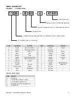
Страница 5: ...tin America T Mandarin China H Portuguese Portugal U Restricted I Not Used V English Pacific Rim Korea J Danish Denmark W English Middle East K Dutch French Belgium X Not Used L Dutch Netherlands Y Not Used M Greek Greece Z Not Used AGENCY CODE TABLE CODE AGENCY N No Agency E CE RoHS compliance combined U US Canada compliance only A Advantage style oven to be phased out B Australia AGA Panel Setup...

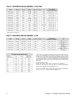
Страница 6: ...N G 40 000 BTU at 11 inches H2O column 1154 xxx U Kxxx Nat Gas Hs 13 KW 230 VAC 2 Amps 1 50 Hz 3 Wires 1 Pole N G Hs 13 KW HR at 1 7 kPa H2O column 1155 xxx U Kxxx L P Gas Hs 13 KW 230 VAC 2 Amps 1 50 Hz 3 Wires 1 Pole N G Hs 13 KW HR at 2 73 kPa H2O column 1178 xxx U Kxxx Nat Gas 40 000 BTU 120 VAC 7 Amps 1 60 Hz 3 Wires 1 Pole N G 40 000 BTU at 7 inches H2O column GAS PRESSURE CONVERSION CHART I...

Страница 7: ...s steel belt travel distances of 52 inches 1320 mm with 24 inches 610 mm in the baking area Conveyor belt width is 18 inches 460 mm Speed range 50 seconds 30 minutes DB LEVEL 70dba OPERATING TEMPERATURE RANGE Gas 300 550 F 149 288 C Electric 200 550 F 93 288 C NOTE Specifications are subject to change Above data should be used for estimating purposes only U S Patent Nos 3 844 213 and 4 154 862 Oth...

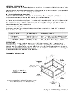
Страница 8: ...WEIGHTS All uncrated components of the Impinger Conveyor Oven will pass through a 30 inch wide door The Impinger Conveyor Oven consists of Cartons or Crates Weight of Each Dimensions of Each 1 oven export 486 lbs 220 5 Kilo 43 x 63 x 24 1104 9 x 1600 2 x 609 6 mm 1 oven domestic 396 lbs 180 0 Kilo 42 x 59 x 23 1066 8 x 1498 6 x 584 2 mm 1 stand export domestic 45 lbs 20 4 Kilo 42 x 26 x 5 1066 8 x...

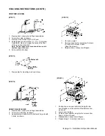
Страница 9: ...ve 2 in front 2 in rear FOR DOUBLE OVEN Step 2 FOR DOUBLE OVEN Step 3 TOP UNIT 1 Remove door conveyor and finger assemblies 2 Turn unit on left side as shown 3 Drill holes in cover as shown Refer to step 3 pg 14 4 Assemble top of bottom unit to bottom of top unit with 4 bolts as shown STACKING UNITS 1 Position top unit over top of bottom unit and align top flanges with bottom unit 2 Replace 4 scre...

Страница 10: ... casters into base 1 Set oven upright 2 Remove oven top by removeing 2 screws in front and 2 screws in back Save the screws 3 Replace door conveyor and fingers 1 Prepare top for mounting as shown above OVEN TO BE STACKED 1 Remove door conveyor and finger assemblies 2 Turn unit on left side as shown 3 Assemble top of bottom unit to bottom of top unit with 4 bolts as shown 1 Position top oven over b...

Страница 11: ...hould be contacted to provide guidance A properly engineered and installed ventilation hood and HVAC system will expedite approval and reduce oven maintenance costs Proper ventilation is the oven owner s responsibility The ventilation hood must operate in harmony with the building HVAC system It typically requires between 750 and 2500 CFM exhaust The Efficiency of various hood designs makes it nec...

Страница 12: ...ia an alternate method of coloring the air may be used 1 Wear heat resistant gloves to prevent burns to your hands 2 Put the smoke candle in a cake pan approximately 8 inches 200 mm x 8 inches 200 mm x 2 inches 50 mm deep or equivalent 3 Open the optional access window in the oven door the oven door or insert candle through conveyor opening 4 Light the fuse of the smoke candle and immediately put ...

Страница 13: ...Gas Codes ANSI Z223 1 NFPA 54 latest version Manufacturers Installation Instructions and local municipal building codes ISO 203 1 1 The oven and its individual shut off valve must be disconnected from the gas supply piping system during any pressure testing of that system at test pressures in excess of psig 3 45kPa 2 The oven must be isolated from the gas supply piping system by closing its indivi...

Страница 14: ...ncoln Foodservice Products LLC Service Representative This service is required by Lincoln Foodservice Products LLC in order to assure the oven s is are properly installed and in working order The warranty becomes effective upon verification of proper installation The warranty shall not apply if the oven s is are started up and operated prior to the START UP CHECKOUT being performed by an Authorize...

Страница 15: ...g the TIME button will show the current setting The speed can be set as follows using the UP or DOWN buttons 1 00 to 9 55 in 5 second increments 10 00 to 12 45 in 15 second increments 13 00 to 19 30 in 30 second increments 20 00 to 30 00 in 1 minute increments For split belt ovens there are set points for each conveyor belt speed While in the setpoint mode pressing the TIME button again will toggl...

Страница 16: ...emperature for immediate use when needed Currently AutoQuest will activate after 14 minutes of inactivity during normal daily operation or 34 minutes after the unit is first turned on in the morning 20 minute oven warm up 14 minutes You will notice that once AutoQuest has been activated the following will occur Conveyor Belt will stop moving Fan Motor will slow down noticeably quiet Quest light wi...

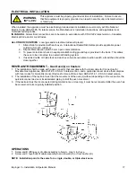
Страница 17: ...ground lug is provided in the back This allows the oven to be connected to an external bonding system 4 If used as double or triple stack and each oven has its own disconnection switch all switches should be close together RESTRAINT REQUIREMENT Gas Oven s on Casters 1 The installation shall be made with a gas connector that complies with the local codes for Connectors for Movable Gas Appliances AN...

Страница 18: ... Grasp top finger housing lift up from bracket and pull forward 3 Grasp bottom finger housing handle and pull forward sliding assembly out of oven BOTTOM FINGER ASSMBLY 4 Slide finger cover from housing Lift out inner Columnating Plate TOP FINGER ASSMBLY 5 Reassemble in reverse order Be sure finger assembly seats securely over rear openings 1 Open Door NOTE Door may be removed by lifting from hing...

Страница 19: ...switch off and disconnect the oven from the electrical supply No electrical components should be subjected to moisture It is therefore important that the oven is wiped down carefully NEVER throw buckets of water over the oven or subject it to pressure washing from a hose or a pressure spray If water or other liquid is spilled on the oven make sure that none has entered the control box area before ...

Страница 20: ...ating You must discuss the need for Preventive Maintenance with your Authorized Service Company to establish a proper program If there is any question the service company cannot answer contact the Lincoln Foodservice Product LLC Service Department HOW TO OBTAIN SERVICE If the oven fails to operate check the circuit breaker to be sure it is turned on on a gas oven check the manual gas valve to insu...

Страница 21: ...TCH TIMER TRANSFORMER DANGEROUS VOLTAGE EQUIPOTENTIALITY GROUND PROTECTIVE EARTH GROUND EARTH GROUND CHANGE FUSES FUSE POWER OFF POWER ON DISCONNECT POWER TEMPERATURE HEAT CONVEYOR FAN BURNER HEAT CYCLE READY TIMER INDICATOR RESET HIGH TEMPERATURE HEAT APPENDIX A LABEL DEFINITIONS ...

Страница 22: ...I Installation Operation Manual 22 APPENDIX A LABEL DEFINITIONS CONT D AMPS VOLTS KILOWATTS HR TYPE OF GAS AC COOK TIME SERVICE ACCESSIBILITY PROVIDE MINIMUM REAR AND SIDE CLEARANCE ORIFICE MAIN ORIFICE LOW FIRE ...

Страница 23: ...gations associated therein null and void This includes any damage costs or legal actions resulting from the installation of any Lincoln commercial cooking equipment in a non commercial application or installation where the equipment is being used for applications other than those approved for by Lincoln LIMITATIONS OF LIABILITY The preceding paragraphs set forth the exclusive remedy for all claims...

Страница 24: ...Impinger II Installation Operation Manual 24 ...

Отзывы: