vi
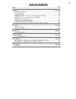
TAbLE OF CONTENTS
Page
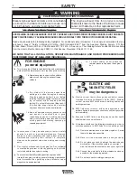
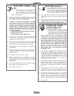
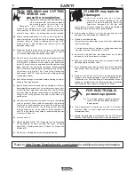
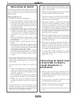
Safety
.......................................................................................................................................i-iv
Installation.......................................................................................................................Section A
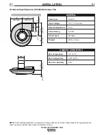
Technical Specifications .......................................................................................................A-1
Safety Precautions ...............................................................................................................A-3
General Description..............................................................................................................A-3
Installing with an LFA, 10ft. or 13ft. Wall-mounted Arm Package ........................................A-3
Installing with an LTA 2.0, Telescopic Arm Package ...........................................................A-7
Installing the optional Silencer............................................................................................A-10
Installing the optional Statiflex 200-M.................................................................................A-10
Installing the Starter/Overload Switch ................................................................................A-11
Installing the optional Lamp Kit and Automatic Start/Stop Arc Sensor...............................A-11
Operation.........................................................................................................................Section b
Safety Instructions ................................................................................................................B-1
Operating Instructions ..........................................................................................................B-1
Maintenance ....................................................................................................................Section C
Routine Maintenance ...........................................................................................................C-1
Trouble Shooting ............................................................................................................Section D
Trouble Shooting Chart ........................................................................................................D-1
Wiring Diagram ...............................................................................................................Section E
Wiring Diagram for SF2400 Fan with K1494-2 Starter/Overload Switch..............................E-1
Wiring Diagram for SF2400 Fan with K1669-2 Lamp Kit .....................................................E-2
Parts Manual ..................................................................................................................Appendix
Parts Pages ..........................................................................................................................1-4
Содержание SF2400 STATIONARY FAN IM622
Страница 27: ...NOTES SF2400 STATIONARY FAN ...


