


English
English
7
System Connection
System Overview
The Power Wave
®
AC/DC 1000 SD CE power source is
designed to be a part of a modular welding system
typically controlled by a MAXsa™ 10 Controller or a
customer supplied Programmable Logic Controller
(PLC). Each welding arc may be driven by a single
power source or by a number of power sources
connected in parallel. The actual number of power
sources per arc will vary depending on the application.
When only one power source is required for an arc
group, it must be configured as a Master. When parallel
machines are required, one is designated as the Master
and the rest as Slaves. The synchronizing connectors for
paralleled machines are on the back of the power
source. The Master controls the AC switching for the arc
group, and the Slaves respond accordingly. See Figure
#3 below.
When employed in a multi-arc AC system the arcs must
be synchronized to each other. The Master for each arc
can be configured to follow a dedicated external
synchronization signal to determine its frequency and
balance. The Synchronizing Connectors on the back of
the Power Wave
®
AC/DC 1000 SD CE provide the
means to synchronize the AC wave shapes of up to six
different arcs to a common carrier frequency. (See
Figure #3). This frequency can range from 20 hertz to
100 hertz. It can also control the phase angle between
arcs to reduce the effects of welding related issues such
as "Arc Blow".
The arc to arc phase relationship is determined by the
timing of each arc’s "sync" signal relative to the "sync"
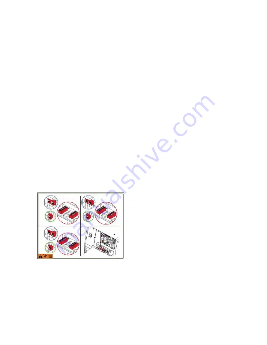
signal of ARC 1. DIP Switches on the Control PC Board
of each machine must be set to identify it as a Master
Lead, Master Trail or Slave. See Figure #2.
Figure #2: Dip Switch Settings
In a typical multi-arc system, each arc is controlled by its
own MAXsa™10 Controller. The basic characteristics of
the individual arcs such as WFS, amplitude, and offset
are set locally by each arc’s dedicated controller. The
frequency, balance, and phase shift parameters of each
arc are controlled by the MAXsa™ 10 Controller for ARC
1 (Master Lead).
NOTE:
The K2803-1 Power Wave
®
AC/DC 1000
®
SD
is backwards compatible with the K2344-2 Power
Wave
®
AC/DC 1000 in tandem or multi-arc systems.
The K2803- 1 and K2344-2 machines cannot be
connected in parallel. Paralleled machines must be of
the same type. A K1805- 1 (14 to 22 pin adapter cable)
is required to interface to the K2282-1 Systems Interface
in these setups A PLC interface is an alternate method
of control for larger systems. The PLC is typically
connected via DeviceNet directly to the Master power
source of each arc group in the system. MAXsa™ 19
Controller is still required to power the Wire Drive.
Contact your Local Lincoln Electric Representative for
more information.
The connection diagrams describe the layout of several
typical systems including Multi-Arc and Paralleled
machine set-ups. Each system also has a step by step
“Installation Checklist”.
MASTER-LEAD MASTER-TRAIL
SLAVE
Содержание K2803
Страница 11: ...English English 8 Cruiser Connection Diagram...
Страница 13: ...English English 10 Single Arc Connection Diagram...
Страница 15: ...English English 12 Tandem Arc Connection Diagram...
Страница 17: ...English English 14 Paralleling Connection Diagram...
Страница 19: ...English English 16 MAXsa 19 Connection Diagram...


