


B-18
OPERATION
AIR VANTAGE
®
600X-I
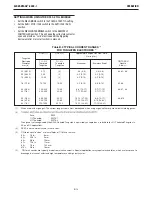
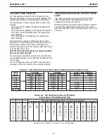
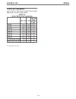
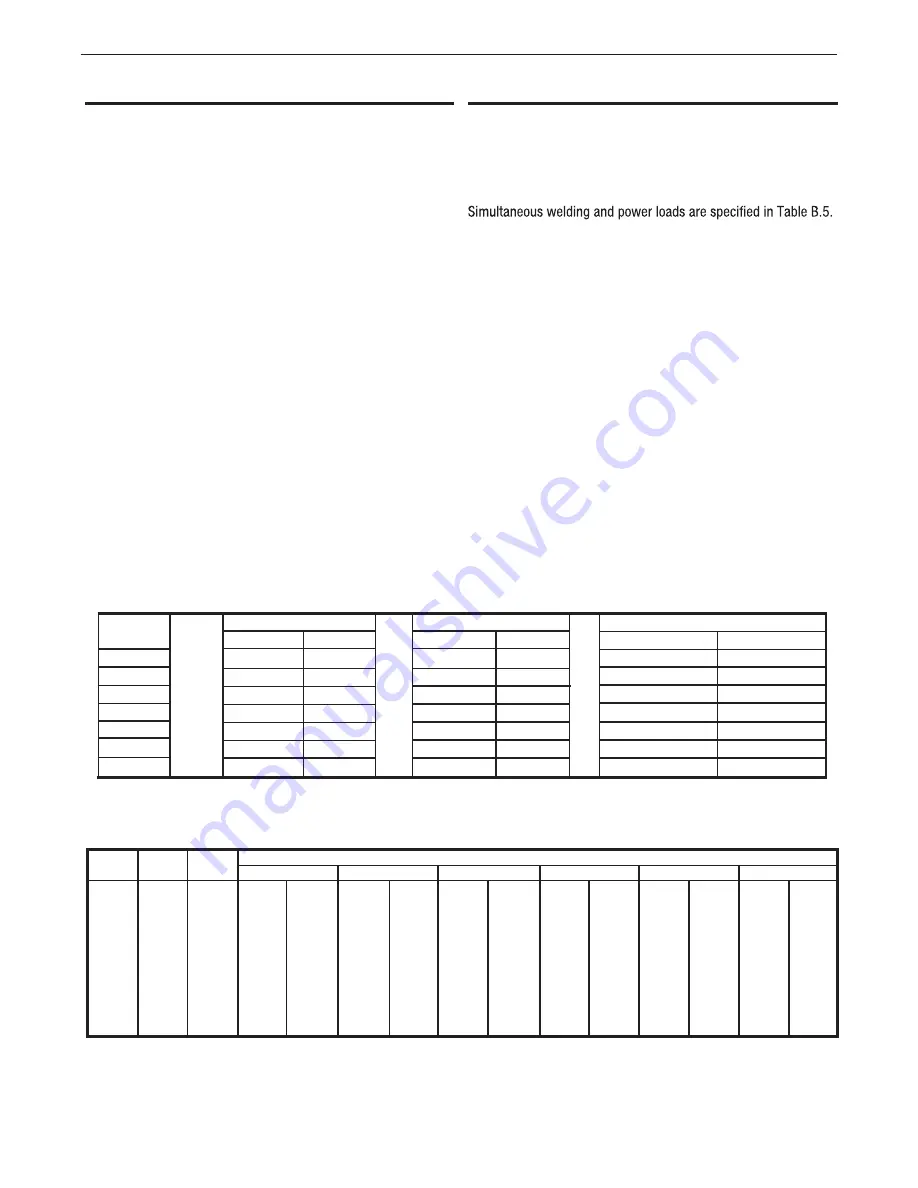
TABLE B.6 AIR VANTAGE® 600X-I EXTENSION
CORD LENGTH RECOMMENDATIONS
Current
(Amps)
15
15
20
20
25
30
38
50
Voltage
(Volts)
120
240
120
240
240
240
240
240
Load
(Watts)
1800
3600
2400
4800
6000
7200
9000
12000
30
60
(9)
(18)
40
75
30
60
(12)
(23)
(9)
(18)
75
150
50
100
90
75
(23)
(46)
(15)
(30)
(27)
(23)
125
225
88
175
150
120
100
(38)
(69)
(27)
(53)
(46)
(37)
(30)
175
350
138
275
225
175
150
125
(53)
(107)
(42)
(84)
(69)
(53)
(46)
(38)
300
600
225
450
250
300
250
200
(91)
(183)
(69)
(137)
(76)
(91)
(76)
(61)
Maximum Allowable Cord Length in ft. (m) for Conductor Size
Conductor size is based on maximum 2.0% voltage drop.
14 AWG
12 AWG
10 AWG
8 AWG
6 AWG
4 AWG
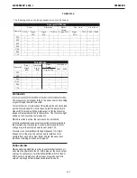
TABLE B.5 AIR VANTAGE 600X-I SIMULTANEOUS WELDING AND POWER LOADS
WELD
AMPS
0
100
200
250
300
400
Up to 600
1 PHASE
WATTS
AMPS
7,800 20
7,800 20
7,800 20
7,800 20
7,800 20
5,600 14
0 0
3 PHASE
WATTS
AMPS
20,000 50
17,600 43
14,400 35
12,500 30
10,400 25
5,600 14
0 0
BOTH 1 AND 3 PHASE
WATTS
------
50
------
50
------
50
12,500 ------
10,400 ------
5,600 ------
0 0
PLUS
OR
OR
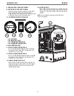
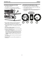
AUXILIARY POWER OPERATION
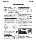
Start the engine and set the RUN / STOP / IDLE switch to the
desired operating mode. Full power is available regardless of the
welding control settings, if no welding current is being drawn.
The auxiliary power of the Air Vantage
®
600X-I consists of the
following:
- One 20 amp 120 VAC (NEMA 5-20R) duplex receptacle with
GFCI protection
The auxiliary power capacity is 7,800 watts of 60 Hz, single
phase power or 20,000 watts of 60 Hz, three phase power. The
auxiliary power capacity rating in watts is equivalent to volt-
amperes at unity power factor. The maximum permissible current
of the 240 VAC output is 50 A.
NOTE: The 120V and 240V receptacles are connected to different
phases and cannot be paralleled.
The auxiliary power receptacles should only be used with three
wire grounded type plugs or approved double insulated tools with
two wire plugs.
The current rating of any plug used with the system must be at
least equal to the current capacity of the associated receptacle.
SIMULTANEOUS WELDING AND AUXILIARY POWER
LOADS
The auxiliary power capacity previously stated is maintained
without any welding load. If a welding load is present, the
available auxiliary power will decrease.
The permissible currents shown assume that current is being
drawn from either the 120 VAC or 240 VAC supply (not both at the
same time).
- One 50 amp 240 VAC (NEMA 15-50R) single phase receptacle
- One 15 amp 120 VAC (IEC 60309 Yellow 2P+Ground) single
phase receptacle
- One 15 amp 240 VAC (IEC 60309 Blue 2P+Ground) single
phase receptacle
AMPS


