

INSTALLATION
AIR VANTAGE
®
600X-I
A-8
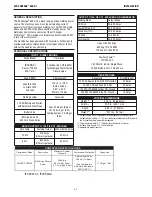
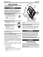
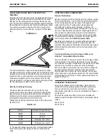
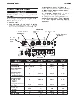
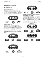
CABLE INDUCTANCE AND ITS EFFECTS ON
WELDING
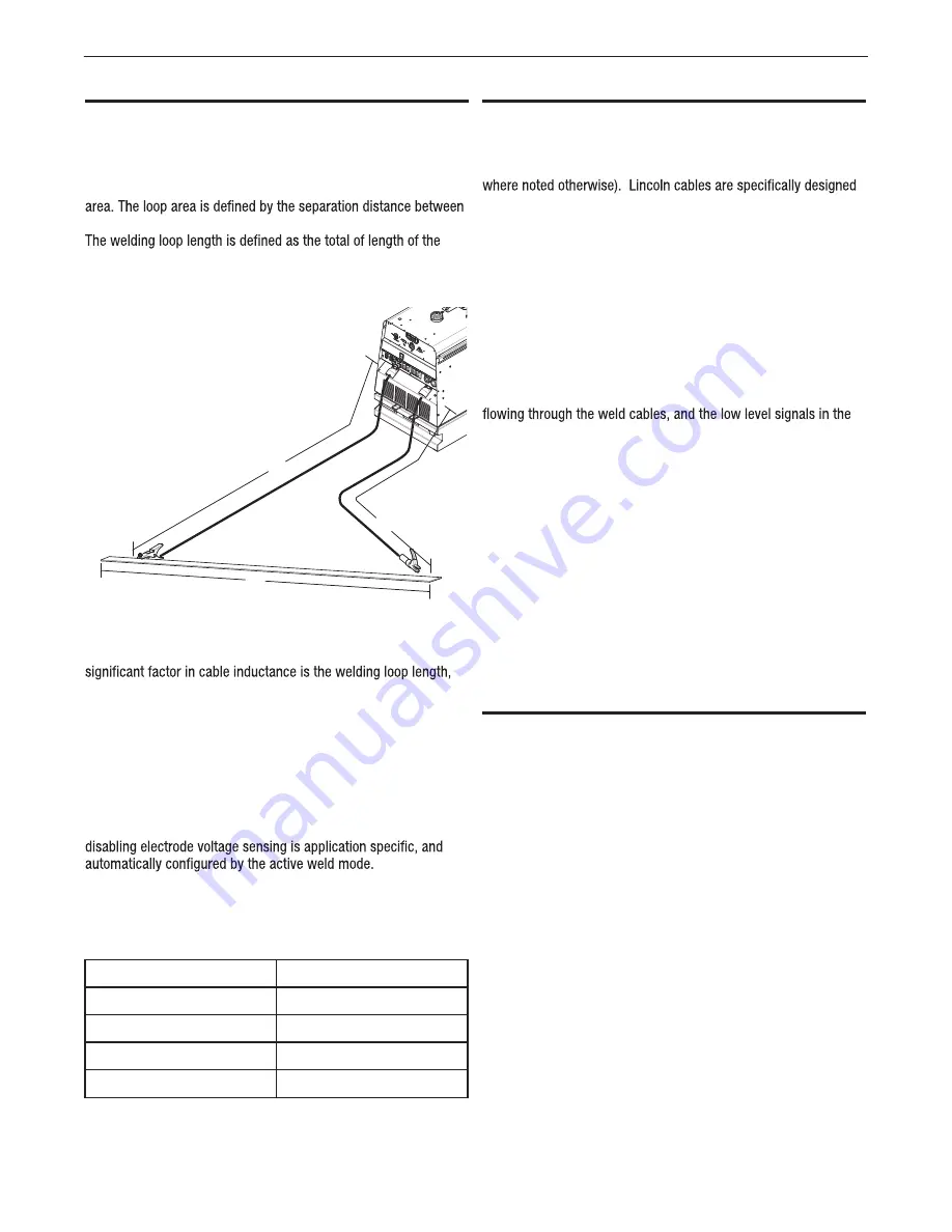
Excessive cable inductance will cause the welding performance to
degrade. There are several factors that contribute to the overall
inductance of the cabling system including cable size and loop
the electrode and work cables and the overall welding loop length.
electrode cable (A) + work cable (B) + work path (C) (See Figure
A.5).
FIGURE A.4
To minimize inductance always use the appropriate size cables,
and whenever possible, run the electrode and work cables in close
proximity to one another to minimize the loop area. Since the most
avoid excessive lengths and do not coil excess cable. For long
work piece lengths, a sliding ground should be considered to keep
the total welding loop length as short as possible.
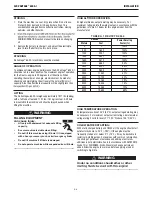
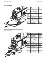
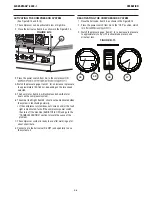
Electrode Voltage Sensing
The remote electrode sense lead (67) is built into the 5-pin
ArcLink control cable and is always connected to the wire drive
feed plate when an ArcLink wire feeder is present. Enabling or
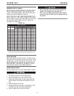
Voltage sense leads requirements are based on the weld process
(See Table A.3)
TABLE A.3
(1) The electrode voltage sense lead (67) is automatically enabled
by the weld process, and integral to the 5 pin ArkLink control
cable.
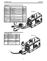
CONTROL CABLE CONNECTIONS
General Guidelines
Genuine Lincoln control cables should be used at all times (except
for the communication and power needs of the engine driven
welder and Power Feed
®
systems. Most are designed to be
connected end to end for ease of extension. Generally, it is
recommended that the total length not exceed 200 ft (61 m). The
use of non-standard cables, especially in lengths greater than 25
feet, can lead to communication problems (system shutdowns),
poor motor acceleration (poor arc starting), and low wire driving
force (wire feeding problems). Always use the shortest length of
control cable possible, and
DO NOT coil excess cable.
Regarding cable placement, best results will be obtained when
control cables are routed separate from the weld cables. This
minimizes the possibility of interference between the high currents
control cables.
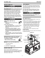
Connection Between Air Vantage
®
600X-I and
ArkLink
The 5-pin ArcLink
®
control cable connects the Air Vantage
®
600X-I
to the wire feeder. The control cable consists of two power leads,
one twisted pair for digital communication, and one lead for voltage
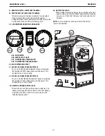
sensing. The 5-pin ArcLink
®
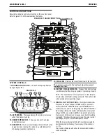
connection on the Air Vantage
600X-I is located on control panel. The control cable is keyed and
polarized to prevent improper connection. Best results will be
obtained when control cables are routed separate from the weld
cables, especially in long distance applications. The recommended
combined length of the ArcLink
®
control cable network should not
exceed 200 ft (61 m).
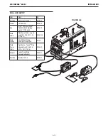
CROSSLINC TECHNOLOGY
This machine features CrossLinc technology, which allows for
remote control of the welding output via the weld cables rather
than a control cable. As result, the control cable is no longer
needed when connected to a CrossLinc compatible wire feeder or
remote control.
This machine will function with all CrossLinc compatible wire
feeders except for the oldest LN-25X models. Incompatible models
include:
Code # 12432
Code # 12504
C
B
A
Process
Electrode Voltage Sensing (1)
GMAW
67 lead
FCAW
67 lead
GTAW
Voltage sense at studs
SMAW
Voltage sense at studs
®
Compatible Wire Feeders
®


