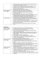
4. Check fuel supply to burner is ok. Gas supply can occasionally be low
check with local gas supplier if required.
5. Check gas pressure regulator is set correctly. Gas pressure regulator
must have the vent to atmosphere free from any obstruction.
6. UV flame scanner is not seeing the main flame, check that UV flame
scanner is aiming at the flame.
7. Defective flame safeguard, replace if required.
High fire cannot be
achieved
(gas)
1. Main gas supply pressure is low, contact gas supplier.
2. Gas isolation cocks partially closed in gas line, open fully.
3. Check gas throughput at gas meter and check with original
commissioning report.
4. Make sure gas pipe is sized correctly and is not obstructed.
5. Check that gas pressure regulator is correctly sized and regulator spring
is adjusted to the same pressure as originally commissioned.
6. Check gas pressure regulator is set correctly. Gas pressure regulator
must have the vent to atmosphere free from any obstruction.
CO being formed
1. Gas flame is impinging on combustion chamber surface, ensure that
correct fuel/air ratios and combustion is set correctly, the burner may be
over fired, reduce gas flame to the correct input.
2. Check for correct fuel/air ratios and combustion is set correctly, O2 values
should read in between 2 to 3% without making CO. Re-adjust gas/air
ratios to correct CO condition.
3. Adjust gas injection gap to improve gas/air mixing at the combustion
head.
Oil specifics
Burner pilot lights
but main fuel
(oil)
does not light
1. Oil supply is turned off. Turn on main gas isolation cocks.
2. Oil solenoid valves faulty, check valves open when energized.
3. Oil valves faulty, check wiring connections.
4. Check fuel supply to burner is ok. Oil supply from local tank could be
isolated or tank could be empty.
5. Check oil pump is rotating correctly in the correct direction. Check motor
wiring connections, check motor windings for integrity, check motor to
pump coupling.
6. Check oil pressure regulator is set correctly.
7. Check oil filter is clean and unobstructed, replace if required.
8. UV flame scanner is not seeing the main flame, check that UV flame
scanner is aiming at the flame.
9. Defective flame safeguard, replace if required.
High fire cannot be
achieved
(oil)
1. Main oil supply pressure is low, check oil supply line for tank.
2. Oil isolation cocks partially closed in oil line, open fully.
3. Check oil throughput at oil meter and check with original commissioning
report.
4. Make sure oil pipe is sized correctly and is not obstructed.
5. Check that oil pressure regulator is correctly sized and regulator spring is
adjusted to the same pressure as originally commissioned.
6. Check oil pump is rotating correctly in the correct direction. Check motor
to pump coupling is tight.
Oil flame producing
black smoke
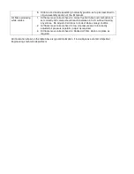
1. Oil flame is impinging on the combustion chamber surface, ensure that
the flame is not over fired, reduce oil flame to the correct input.
2. Check for correct fuel/air ratios and combustion is set correctly, O2 values
should read in between 3 to 4% without making any smoke. Re-adjust
oil/air ratios to correct smoky condition.
3. Faulty nozzle or blocked nozzle, clean or replace as required.
4. Oil pressure too high, check oil pump and oil pressure regulator for correct
adjustment.
Содержание LC Series
Страница 3: ...Section 1 Legal statements and Disclaimers Burner assembly area ...
Страница 7: ...Section 2 Burner Technical Data Gas flame firing at 12 300 000 btu hr ...
Страница 9: ...Section 3 Component Information General assembled burner ...
Страница 11: ...Section 4 Gas Manifold assembly Split gas head assembly ...
Страница 16: ...Section 5 Oil Gun assembly Oil nozzle and lance assembly ...
Страница 19: ...Section 6 Electrode settings Pilot injector and ignition setup ...
Страница 22: ...Section 7 Burner Installation Limpsfield LC9 dual fuel burners on Hurst boilers ...
Страница 24: ...Sample Typical fire tube installation ...
Страница 25: ...Typical water tube installation ...
Страница 29: ...Section 8 Typical Gas control Train 2 gas control train assembled ...
Страница 32: ...Section 9 Typical Oil Train Assembled oil pump with filter ...
Страница 36: ...Section 10 General start up procedure ...
Страница 43: ...Section 11 Service Recommendations ...
Страница 47: ...Section 12 General Burner Servicing Procedure ...
Страница 52: ...Section 13 Fault Finding ...
Страница 56: ...Section 14 Commissioning Report ...


