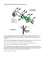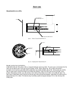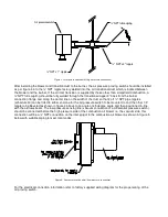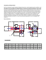
Step 5: Once the desired gap has been obtained, tighten jam screws/washers as illustrated in Figure 6. The
washer, once tight, should compress against the head of the gap adjusting screw (item 3). Ensure that this is
the case. Replace washer as needed if compression does not take place.
Step 6: After jam screws/washers have been installed, re-assemble diffuser and diffuser stand off pillars to
their original position. Install pilot injector disc, setting the gap to its original position (1/8” or 3mm). DO NOT
FORGET TO TIGHTEN SET SCREW, located in the pilot injector body.
IMPORTANT NOTE:
Adjustments in the orifice plate gap setting will change the gas flow rate (hence, gas pressure) from their
original values. DECREASING the gap will allow less gas flow per the same pressure. Likewise,
INCREASING the gap will allow more gas flow per the same pressure. Thus, the burner fuel/air ratio may
change and require alterations to be made from the original commissioned values. Refer to the Autoflame
Technical Manual and the “Single Point Change Facility” for assistance. If in doubt, a re-commission should
be carried out.
Only trained service personnel should make adjustments in the orifice plate gap setting. Call your local
service company for assistance in making any adjustments to any piece of combustion equipment.
Figure 5: Gas Adjustment
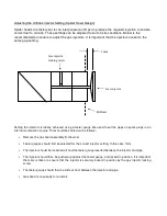
Figure 6: Jam Screw/Washer
"T"
Ha
nd
le A
llen
W
ren
ch
Gap
Setti
ng
3
4
Gap Adjusting Screw
Jam Screw/ Washer
Содержание LC Series
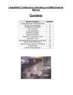
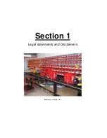
Страница 3: ...Section 1 Legal statements and Disclaimers Burner assembly area ...
Страница 7: ...Section 2 Burner Technical Data Gas flame firing at 12 300 000 btu hr ...
Страница 9: ...Section 3 Component Information General assembled burner ...
Страница 11: ...Section 4 Gas Manifold assembly Split gas head assembly ...
Страница 16: ...Section 5 Oil Gun assembly Oil nozzle and lance assembly ...
Страница 19: ...Section 6 Electrode settings Pilot injector and ignition setup ...
Страница 22: ...Section 7 Burner Installation Limpsfield LC9 dual fuel burners on Hurst boilers ...
Страница 24: ...Sample Typical fire tube installation ...
Страница 25: ...Typical water tube installation ...
Страница 29: ...Section 8 Typical Gas control Train 2 gas control train assembled ...
Страница 32: ...Section 9 Typical Oil Train Assembled oil pump with filter ...
Страница 36: ...Section 10 General start up procedure ...
Страница 43: ...Section 11 Service Recommendations ...
Страница 47: ...Section 12 General Burner Servicing Procedure ...
Страница 52: ...Section 13 Fault Finding ...
Страница 56: ...Section 14 Commissioning Report ...


