background image


Page 8 / 15 

Section 

5

. Web control 

– Using the Built-in website 


5.2.  IP settings 

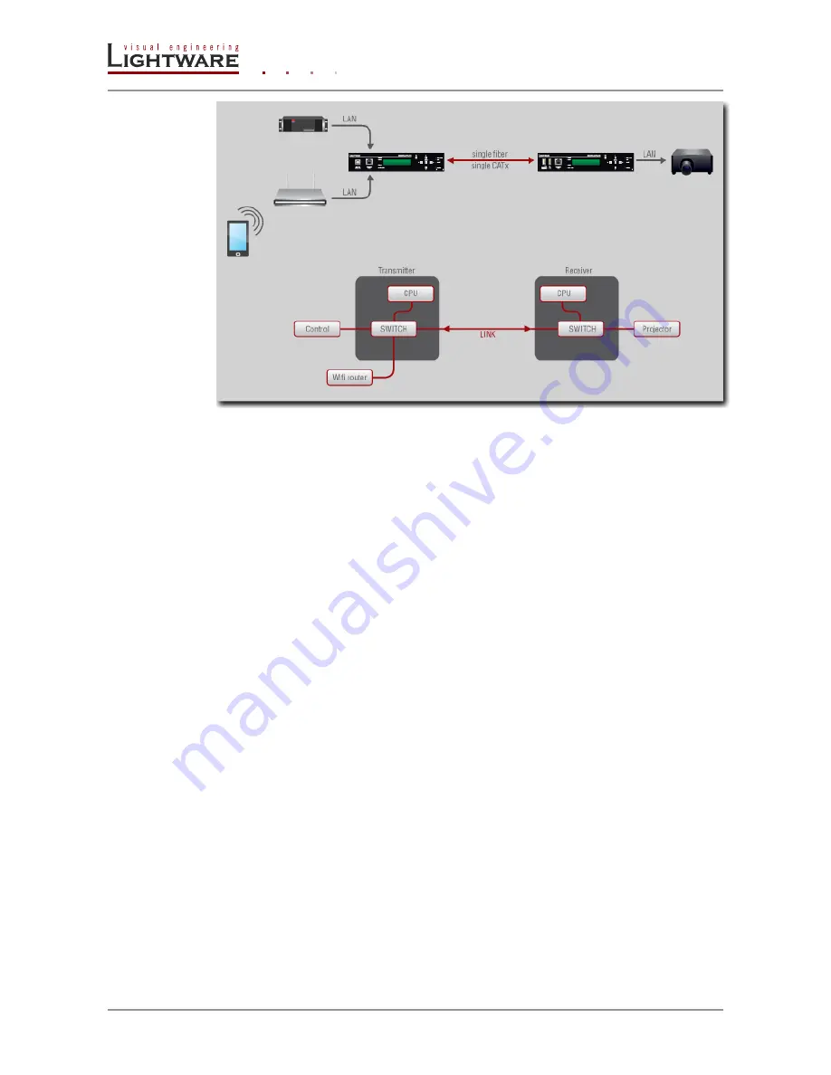
Before you connect to a MODEX extender using a Web browser the IP address must be 
set.  The  Ethernet  port  can  be  configured  on  the  front  panel  LCD  menu  or  remotely 
through the built-in website. There are three different ways to configure the IP address.  

Set the factory default IP address 

MODEX  extenders  have  static  IP  settings  at  the  first  startup.  You  can  reload  these 
settings  to  the  default  state  by  setting  the  factory  default  on  the  LCD  menu  (Settings/ 
System/ Factory Default) or on the built-in website (Settings/ Network). 

Transmitter:  

IP address: 

192.168.0.101 

port number: 

6107  

subnet mask: 

255.255.255.0 

gateway:   

192.168.0.1 

HTTP port: 

80 

WEB socket: 

81 

Receiver:  

IP address: 

192.168.0.102 

port number: 

6107  

subnet mask: 

255.255.255.0 

gateway:   

192.168.0.1 

HTTP port: 

80 

WEB socket: 

81 

Set a user defined static IP address 

The IP address, Subnet mask, Static gateway and the Port number can be set by a user 
defined  value  on  the  front  panel  LCD  menu  (Settings/  Network  Settings)  or  remotely 
through the built-in website (Settings/Network). 

Set a dinamic IP address 

DHCP  mode  can  be  enabled  on  the  front  panel  LCD menu  (Settings/  Network Settings/ 
DHCP) or remotely through the built-in website (Settings/Network/DHCP). The extenders 
acquire IP addresses from the DHCP server on the LAN in this case. 

5.3.  Establishing the connection 

To connect to a Modex launch a web browser and type the IP address. You can verify the 
actual  address  of  the  Modex  unit  on  its  front  panel  display  (Settings/Network).  See 
previous chapter for available options. 

Содержание Modex-Rx

Страница 1: ...MODEX TX MODEX RX Modular Extender family MODEX Quick Start Guide ...

Страница 2: ...GENERAL DESCRIPTION 5 2 1 FRONT VIEW 5 2 2 REAR VIEW 6 3 INSTALLATION 6 4 FRONT PANEL OPERATIONS 7 5 WEB CONTROL USING THE BUILT IN WEBSITE 7 5 1 NETWORK STRUCTURE 7 5 2 IP SETTINGS 8 5 3 ESTABLISHING THE CONNECTION 8 5 4 BUILT IN WEB 9 5 4 1 Main menu 9 5 4 2 Crosspoint menu 9 5 4 3 EDID menu 14 5 4 1 Settings 15 6 WARRANTY 15 7 DOCUMENT REVISION HISTORY 16 ...

Страница 3: ...ting the AV and broadcast industry s formats It is capable of extending digital and analog audio and video USB KVM Ethernet and control signals like RS 232 RS 422 IR etc 1 1 Box contents Quick Start Guide this document MODEX Transmitter or Receiver unit IEC Power cable UTP LAN cable Four rubber foot Infrared transmitter and receiver pair 5 pole male phoenix connector 1 2 Typical applications ...

Страница 4: ...ly of each other The MODEX is fully compatible with the 25G hybrid architecture 2 1 Front view USB KVM1 1x USB B connector is on the TX side and 2x USB A connectors are on the RX side USB KVM USB connection to HOST Computer on the TX unit and for two devices e g Keyboard on the RX unit Ethernet Ethernet connection for control and transfer Link status LEDs Audio LED lights green when the audio tran...

Страница 5: ...ver Both devices can be accessed and controlled through either Ethernet port Step 5 Optionally for Ethernet extension connect some Ethernet devices e g switch laptop computer etc to the transmitter and to the receiver All connected devices will work as if they are connected to the same network Step 6 Optionally for RS 232 extension Connect a controller unit e g Touch panel to the RS 232 on TX with...

Страница 6: ...Manufacturer Product Serial VID PID Host info Port2 Manufacturer Product Serial VID PID Host info EDID Presets Load preset Save preset A Modex might have more than one video or interface module of the same kind The appropriate number of branches of the tree appears in this case 5 Web control Using the Built in website Modex transceivers have several configuration options More settings are availabl...

Страница 7: ... 0 1 HTTP port 80 WEB socket 81 Receiver IP address 192 168 0 102 port number 6107 subnet mask 255 255 255 0 gateway 192 168 0 1 HTTP port 80 WEB socket 81 Set a user defined static IP address The IP address Subnet mask Static gateway and the Port number can be set by a user defined value on the front panel LCD menu Settings Network Settings or remotely through the built in website Settings Networ...

Страница 8: ...menu to obtain layers of configuration panel supported by the selected Modex extender pair Note USB KVM has no crosspoint configuration panel Note If a layer is not supported by the selected MODEX then there is no label for its properties 5 4 2 1 Video crosspoint In the main menu left click on the Crosspoint label then left click on Video label the video crosspoint appears The inputs are at the to...

Страница 9: ...ts but only one of these inputs or outputs can be used in the video crosspoint This is because only one video stream transmission is permitted between the core module and the video module After setting the mode of the video interface module the supported input or output port of the selected mode appears in the video crosspoint and the port property becomes available Port property Left click on the...

Страница 10: ...ink can support four audio layers The Embedded audio from Tx to Rx and the Return AUX from Rx to Tx belongs to the Main audio group The Forward Audio from Tx to Rx and Return Audio from Rx to Tx belongs to the S PDIF audio group At the transmitter side the Embedded audio and the Forward Audio appears as an output the Return Audio and the Return AUX appears as an input At the receiver side the dire...

Страница 11: ... Main or S PDIF using the mode function After setting the mode of the audio interface module the supported input and or output port of the selected mode appears in the audio crosspoint and the port property window becomes available The Mode function list is continuously expanding with new features and audio functions and it is possible to implement future costumer needs Port property Left click on...

Страница 12: ...mation about the selected interface module that contains the infra port Port property Left click on the Port property icon a property window opens In the settings list the carrier frequency at the output ports can be set 5 4 2 4 Serial crosspoint In the main menu left click on the Crosspoint label then left click on Serial label the serial crosspoint appears The inputs are at the top row and the o...

Страница 13: ...The Dynamic EDID contains the EDID list of the sinks have been connected to the extenders User EDID contains the user defined EDID list To manipulate EDIDs they can be copied from the left window to the right window Emulate an EDID Step 1 Select if you want to emulate an EDID from the Factory Dynamic or User EDID memories in the left window Step 2 Browse for the desired EDID in the left window and...

Страница 14: ...menu contains general information and status about the core module Network Network parameters can be set See 5 1 section of this document Status Software supply temperature and module information can be read out System log Operational information warnings errors can be read out Backup The extenders support eight preset settings In this menu these presets can be saved and presets can be load USB KV...

Страница 15: ...story 7 Document revision history Document Release Date Changes Editor Rev 1 1 15 05 2013 Front panel operation has changed section 4 Audio group concept has changed section 5 4 2 2 Peter Petrik Rev 1 0 25 03 2013 initial version Peter Petrik ...

Отзывы: