Page 6 / 15
Section
3
. Installation
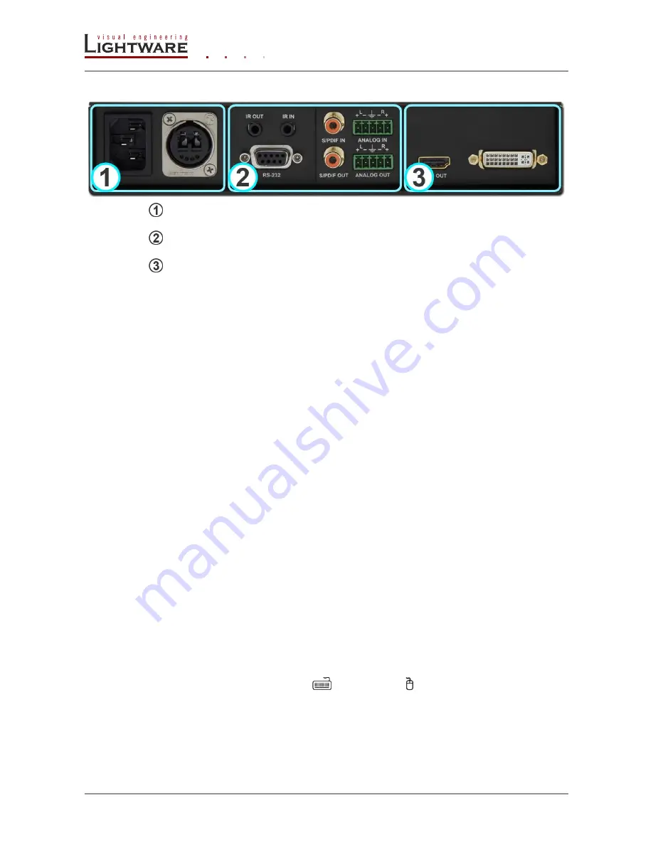
2.2. Rear view
Media connector
User-selected physical connector.
Interface modules
Two user-selected optional interface modules.
Video & audio module
User-selected video and audio module.
3.
Installation
Step 1.
Connect the transmitter and the receiver by using an LC or Neutrik
OpticalCON connector equipped with multi or single mode fiber cable
depending on the Media connector.
Step 2.
Connect a DVI or HDMI source (e.g. computer) to the transmitter's HDMI
INPUT or DVI INPUT connector.
Step 3.
Connect the HDMI or DVI sink (e.g. monitor, projector etc.) to the receiver's
HDMI output. For DVI displays the usage of adaptor cable is necessary.
Step 4.
For controlling the device using the built in WEB page connect a computer
with a LAN patch cable to the Ethernet port of the transmitter or the receiver.
Both devices can be accessed and controlled through either Ethernet port.
Step 5.
Optionally for Ethernet extension:
connect some Ethernet devices (e.g. switch, laptop, computer etc.)
to the transmitter and to the receiver. All connected devices will
work as if they are connected to the same network.
Step 6.
Optionally for RS-232*
extension:
Connect a controller unit (e.g. Touch panel) to the RS-232 on TX
with a null modem serial cable,
Connect a controlled device (e.g. Projector) to the RS-232 on RX
with a regular serial cable.
Step 7.
Optionally for Infra-Red*
extension:
Connect the supplied IR emitter to the IR OUT on TX or RX
Connect the supplied IR detector to the IR IN on TX or RX
Step 8.
Optionally for USB HID* extension:
Connect at least one USB HID* device to the receiver. Use the
keyboard
and the mouse
labeled USB-A connectors.
Connect the transmitter to the computer via the USB-B cable.
Step 9.
Power on the devices using the standard IEC power cable
* Mentioned devices are examples and can be connected to either TX or RX.


