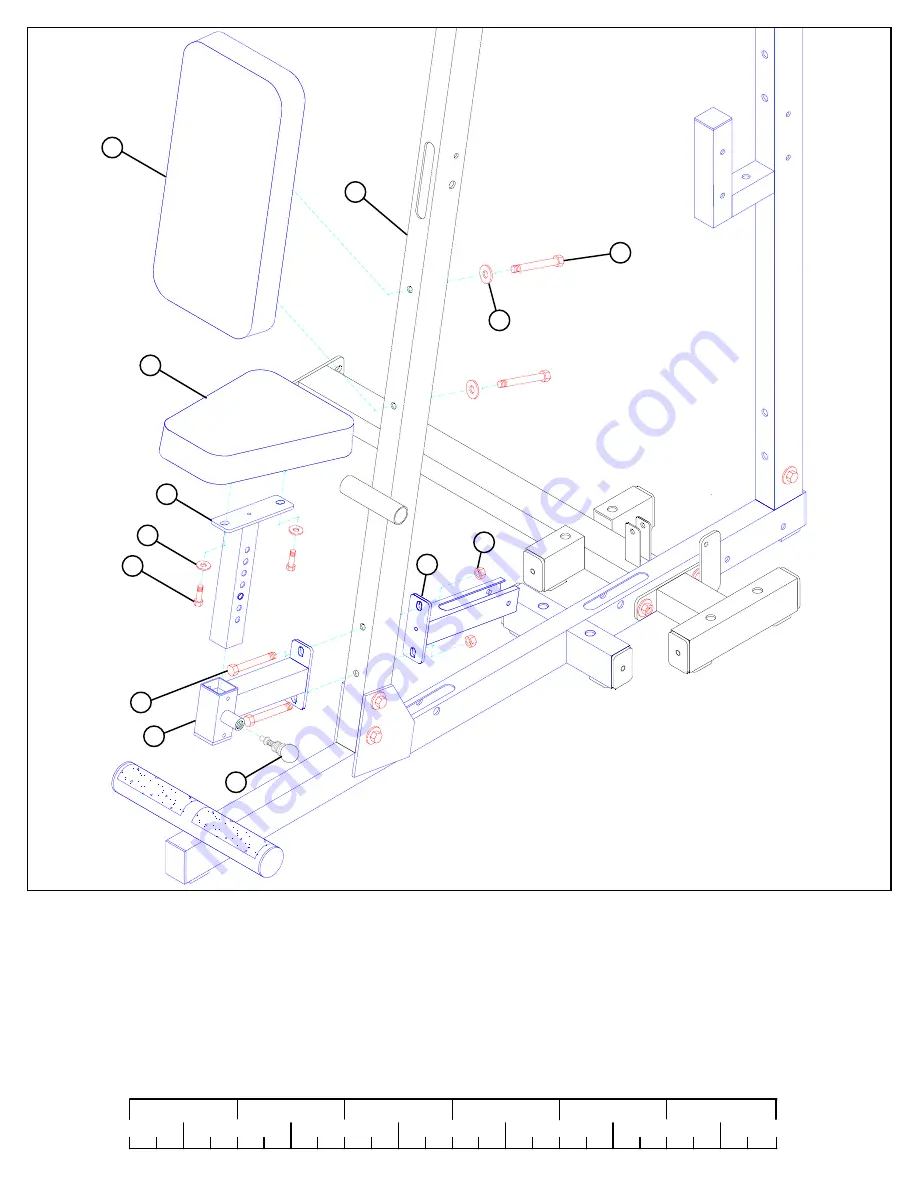
STEP 3:
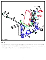
FIGURE 3
6
0
1
2
3
4
5
6
1/2
1/2
1/2
1/2
1/2
1/2
•
SECURELY
assemble the FLOATING PULLEY STOP (11) and the SEAT SUPPORT (12) to the FRONT UPRIGHT (29) using two 1/2
X 4” BOLTS (96) and two 1/2” LOW HEIGHT LOCK NUTS (86) as shown in FIGURE 3.
•
SECURELY
assemble one 3/8 X 2-3/4” SPRING PIN (62) to the SEAT SUPPORT (12) as shown in FIGURE 3.
•
SECURELY
assemble one PEC SEAT PAD (104) to the PAD SUPPORT (13) using two 3/8 X 1-1/4” BOLTS (88) and two 3/8” WASHERS
(80) as shown in FIGURE 3.
•
CAREFULLY
insert the PAD SUPPORT (13) into the SEAT SUPPORT (12) and engage the SPRING PIN into one of the holes.
•
SECURELY
assemble one PEC BACK PAD (105) to the FRONT UPRIGHT (29) using two 3/8 X 4” BOLTS (92) and two 3/8” WASHERS
(80) as shown.
13
104
105
3/8 X 1-1/4” 88
1/2 X 4” 96
92 3/8 X 4”
11
1/2”
LOW
HEIGHT
80
29
62
12
80
86


