background image

Index mark

Mark T

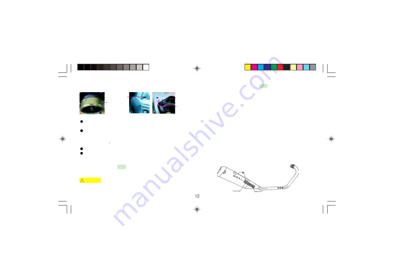
    Fig. 28

Adjusting
screw

Locknut

VALVE CLEARANCE 

(Fig. 28 )

Check valve clearance when the engine is cold at the specified intervals.

Take the top view hole (for ignition timing) cap and magneto cap out of the left cylinder

head cover.

Rotate the flywheel counterclockwise until mark T on the flywheel aligns with the

index mark on the view hole. Check it is in TDC of the compression stroke by moving

the rocker arms. If they are free, it means check can be done. Otherwise, rotate the fly-

wheel through 360

.

Clearance should be 0.08mm for the intake valve and 0.12mm for exhaust valves.
If it is necessary to make an adjustment, loosen the valve lock nut and turn the adjust-

ing screw so there is a slight resistance when the feeler gauge is inserted. Then tighten

up the lock nut, and recheck the clearance.

EXHAUST MUFFLER (EP)

Clear away regularly carbon deposit in the exhaust pipe; check the exhaust pipe inside

for crack and washer for damage, and repair or replace if necessary.

WARNING   Replace the gasket  whenever a muffler is disassembled. The muffler

becomes very hot during operation and remains hot for a while after stopping the

engine. Be careful not to touch the muffler after stopping the engine.

3-WAY CATALYTIC CONVERTER(EP) 

(Fig. 29)

3-way catalytic converter is mounted on the exhaust system of motorcycle. It is designed
to decrease contaminations such as CO, HC, NOx, etc. by redox reaction to catalyst when
the exhaust gases flow through the device.
Applying the catalyst controls the pollutant emissions from the motorcycle, i.e. a chemi-
cal reaction sets in when exhaust gases pass through the converter that contains a catalyst.
The noble metal catalyst is characterised by good adhesiveness, and accelerates a chemi-
cal reaction without itself being affected. Its basic principle is as follow: pollutants in
the exhaust gases, such as CO, CH, NOx, etc, spread into micro-holes in the catalyst when
gases pass through the device, an adsorption reaction happens on the surfaces of catalyst,
as a result, converting them into harmless compounds (CO

2

, H

2

O, N

2

, etc.) and entering

the air. The purging efficiency of catalyst varies with temperature of, density of and speed
of gases.
Attention should be drawn to the following points during service:
1. Handle 3-way catalyst with care, don’t knock or press it, and keep away oil and dirt.
It should be stored in dry and well-ventilated place.
2. Never let acid liquid or electrolyte infiltrate into the exhaust muffler, otherwise, make
the catalyst unefficient.
3. Unleaded gasoline should be used.

Fig. 29

LF 150-10B(ENGLISH)A.p65

2012-4-23, 9:33

15

Содержание LF 150-10B

Страница 1: ...2012 4 23 9 33 1...

Страница 2: ...the operator fails to follow safe operating and maintenance practices Lifan Co will not take any responsibility to any injury or damage occured This manual should be considered as a permanent part of...

Страница 3: ...Parking 8 MAINTENANCE Tool Kit 9 Maintenance Schedule 9 Engine Oil EP 10 Coolant 10 Servicing of Cooling System 11 Clear away Carbon Deposit EP 11 Spark Plug EP 11 Air Cleaner EP 11 Valve Clearance 12...

Страница 4: ...g the motorcycle or removing the original parts MOTORCYCLE SAFE RIDING may make riding unsafe and is illegal also The user must obey all national and local laws and regulations in relation to vehicle...

Страница 5: ...r Main step Radiator Front wheel Front shock absorber Front winker Headlight Meter Rear shock absorber Front brake Gearshift pedal Center stand Side stand Rear wheel Rear winker Pillion rail Seat Fuel...

Страница 6: ...fuel must be unleaded gasoline with octane No RQ 93 or higher Using improper fuel could reduce performance shorten the engine s service life Engine Oil Selection Fig 7 The quality of the engine oil p...

Страница 7: ...IGNITION SWITCH AND STEERING LOCK Fig 9 Ignition Switch The ignition switch is equipped with 2 keys inclucing a spare one OFF Engine and lights cannot be operated and the key can be removed ON Engine...

Страница 8: ...ea is dry before starting the engine KEEP OUT OF REACH OF CHILDREN FUEL COCK Fig 14 The 3 way fuel cock is on the bottom left side of the fuel tank With the fuel cock in the position fuel cannot flow...

Страница 9: ...the vehicle step on the center stand at the left of body while rising the rear portion of body with right hand so as to support the motorcycle Before driving the vehicle move the steering head forward...

Страница 10: ...ystem check for its smoothness and reliability 11 Fastener check that all nuts screws and bolts are mounted securely Correct any discrepancy before you ride Contact your dealer for assistance if you c...

Страница 11: ...r parking turn the ignition switch to position and lock the steeringlock followed by removing the key Attempting to start the engine with the transmission in gear may result in damage to equipment Mak...

Страница 12: ...d be serviecd only by your dealer NOTES Clean more frequently when riding in unusual wet or dusty areas At higher odometer readings still follow the frequency intervals established in this manual MAIN...

Страница 13: ...ine unscrew the drain plug Shift the transmission into neutral operate the starter button several times so as to help empty the oil thoroughly Reinstall the drain plug and tighten it up Pour approx 1L...

Страница 14: ...e surfaces with finger for damage such as ageing cracks If any send it to your dealer for help 2 Check the coolant once every 3000km s drive as following 1 Check the cooland level in the radiator The...

Страница 15: ...uffler after stopping the engine 3 WAY CATALYTIC CONVERTER EP Fig 29 3 way catalytic converter is mounted on the exhaust system of motorcycle It is designed to decrease contaminations such as CO HC NO...

Страница 16: ...decreased speed set the throttle stop screw in the middle between the two limit positions to help mix air and fuel Run the engine again Readjust the throttle stop screw if necessary CAUTION Since the...

Страница 17: ...cylinder Sight glass Screw Cover Brake calliper The front brake lever is located at the right handlebar The distance the front brake lever moves before the brake starts to engage is called free play w...

Страница 18: ...ront wheel pump the front rear shock absorber up and down several times to see that it func tions well without noise or leakage Check the rear fork bushing for proper play by pressing the side of the...

Страница 19: ...prevent short circuiting The leads should be tightened securely or spark may occur to cause a fire Make sure that the duct of battery keeps unblocked or the battery may be explosive under certain con...

Страница 20: ...to prevent surfaces from getting rusty 5 Start the engine and allow it to run for several minutes CAUTION High pressure water can damage certain parts such as wheel bearings front fork brakes seal of...

Страница 21: ...thus reducing the possibility of accidents and protecting personnel and equipment from being injured or damaged In addition avoid the vehicle from being burnt by spilled oil fuel The motorcycle can b...

Страница 22: ...ELECTRICDIAGRAM 2012 4 23 9 33 22...

Страница 23: ...r Coil spring dampened Front brake type Disc operated by hand Rear brake type Disc operated by foot Fuel tank capacity L 13 Reserve capacity 2 ENGINE Model Type Single cylinder 4 stroke water cooled B...

Страница 24: ...2012 4 23 9 33 24...

Отзывы: