background image

19 

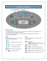
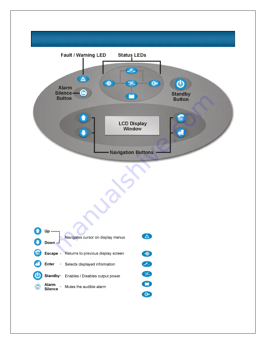
Buttons 

Refer to the legend below in order to properly 
navigate the 

Nfinity 

User Interface. 


LEDs 

Refer to the legend below to indicate occurrence 
when an LED is lit. 


Controls and Indicators 


Display Controls 

The Front Display Panel informs the user of the status of the UPS, and lets him configure the UPS to his 
own needs or preferences through the user interface

It consists of a series of Status LED’s, a 4 line by 20 character LCD display window, and buttons for 
navigation (as displayed above). 


!

Fault / Warning
     Solid- 
     Flashing- 

A UPS fault condition has occured. 

A Warning has occured.  Consult event log. 

AC Input 

- AC utility is available  

On Bypass 

- The Bypass is supplying the power

Inverter On 

- The Inverter is supplying the power

On Battery 

- Battery is supplying power to the inverter 

AC Output 

- Power is available to supply the load

Содержание 12 bay

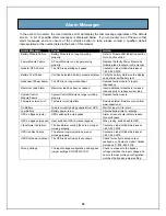
Страница 1: ...User Manual English 208 V 240 V 60Hz 4 to 16 kVA Power System...

Страница 2: ......

Страница 3: ...Handle transport and recycle in accordance with local regulations This UPS is designed for use on a properly grounded earthed 208 240 VAC 60Hz supply and is to be installed by qualified personnel ELE...

Страница 4: ...2 Glossary of Symbols...

Страница 5: ...3 Introduction General Description Modes of Operation Major Components...

Страница 6: ...ovide maximum system availability to business critical equipment Nfinity is also an easily adaptable UPS system By simply installing additional power or battery modules you can expand your current sys...

Страница 7: ...5...

Страница 8: ...ically restart and resume supplying power to the connected equipment This feature is enabled at the factory but can be disabled by the user The user can also program two auto restart delay settings 1...

Страница 9: ...ls By grabbing these bezels from the side and pulling out you will remove the bezel to reveal the Battery Power Module bays The bottom bezel covers the cooling fans and the Manual Bypass Switch The Us...

Страница 10: ...is manual System Control Module The System Control Module is the communicative backbone of the UPS It gathers input from all modules and processes the data to control the operation of the system inclu...

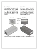
Страница 11: ...ery Modules provide back up power in the event of input utility failure Each module contains a quantity of ten individual 12 volt valve regulated VRLA battery blocks with associated monitoring and con...

Страница 12: ...10 Installation Preparation Unloading Cable Installation Communications...

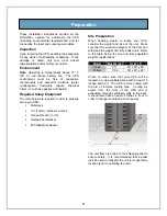
Страница 13: ...in lb Flathead Screwdriver 2 Phillips Screwdriver Site Preparation When deciding where to locate your UPS consider the weight and size of the unit Make sure that the structural integrity of the floor...

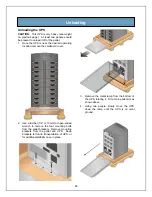
Страница 14: ...ratchet 1 2 or 13mm or open ended wrench to remove the four mounting bolts from the pallet brackets Remove mounting brackets from the pallet and UPS Keep brackets for future transportation of UPS or...

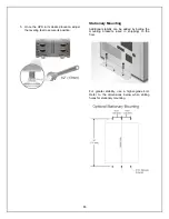
Страница 15: ...eet to secure its position Stationary Mounting Additional stability can be added by bolting the mounting brackets used in shipping to the floor For greater stability use a higher grade bolt Refer to t...

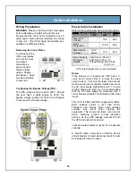
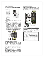
Страница 16: ...urrent 67A phase 77 A 67 A 2 AWG max 35 mm 6 AWG min 16 mm Input Output Terminal Details Torque Rating 22 26 in lb 2 5 3 nm 90 C rated copper wire is recommended Notes If the start up is on bypass the...

Страница 17: ...tors This cable must be green with or without one or more yellow stripes and is to be installed as part of the branch circuit that supplies the unit or system The grounding conductor is to be grounded...

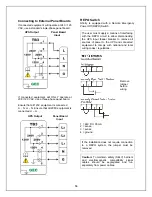
Страница 18: ...ser must supply a means of interfacing with the REPO circuit to allow disconnecting the UPS input feeder breaker to remove all sources of power to the UPS and connected equipment to comply with nation...

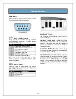
Страница 19: ...ut configuration of the DB 9 connector is Pin Assignment 2 Transmit Data 3 Receive Data 5 Common Intellislot Ports The following communication cards may be used with Nfinity Intellislot SNMP cards all...

Страница 20: ...18 Operating Instructions Controls and Indicators Operating Procedures Main Menu...

Страница 21: ...own needs or preferences through the user interface It consists of a series of Status LED s a 4 line by 20 character LCD display window and buttons for navigation as displayed above Fault Warning Soli...

Страница 22: ...and Output On Normal Operation UPS On Utility Bad and Output On On Battery Operation UPS On Utility Bad and Output Off Unit in Bypass Operation Manual or Automatic Unit in Manual Bypass Operation wit...

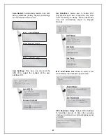
Страница 23: ...our rows of information you may see an arrow on the display pointing up or down as shown below indicating to scroll using the or buttons If you are scrolling through any of the main menus items will s...

Страница 24: ...quest to disable the output by pressing 3 Turn off the Enable Switch SW2 Open the Input Circuit Breaker CB1 Manual Transfer to Bypass In the event of a UPS overload or failure the UPS will transfer to...

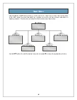
Страница 25: ...on the status of the UPS review the event and alarm log configure your UPS and even receive instructions on replacing modules The main menu is divided into five sub menus as shown below Use the butto...

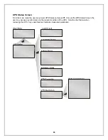
Страница 26: ...u the user may select UPS Status and press Once at the UPS Status Screen the user may access any information on the present condition of the UPS Note the chart below when reviewing the UPS Any underli...

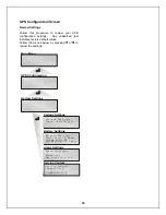
Страница 27: ...llow the menus below by pressing or to review the settings Voltage Settings Input 208 120 LLG Battery Settings Test intervl weeks on at Low Batt Warn min 2 Wed 06 00 2 Alarm Settings Power Max Load kV...

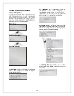
Страница 28: ...bypass voltage jumper setting Set Password Set a Password to prevent unauthorized users from changing the configuration of the Nfinity It can be up to 7 characters in length Once set the password wil...

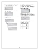
Страница 29: ...rface LCD Set Date Time Allows user to enable DST Daylight Savings Time change the Day Date and Time setting on Nfinity When enabled the time will automatically adjust to Daylight Savings Max Load Ala...

Страница 30: ...Shutdown If you are using SiteNet software this parameter should be enabled in order for the UPS output to be turned off once the operating system has been shutdown External Battery Sets total amp hou...

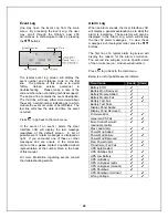
Страница 31: ...ive at the number listed in the back of this manual For more information regarding events consult the troubleshooting section Alarm Log When an alarm sounds the User Interface LCD will display a gener...

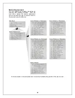
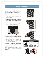
Страница 32: ...tions for removing and replacing modules From the main menu access the module replacement screen and select the type of module Refer to the screens below for reference For more details on module repla...

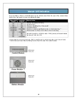
Страница 33: ...31 Troubleshooting Alarm Messages Module LED Indication Module Replacement...

Страница 34: ...itional modules to increase load capacity or reduce current load System Control Module Failure System Control Module no longer working properly Replace faulty module Firmware version error Firmware is...

Страница 35: ...peration FLASHING FLASHING Module is in start up qualification mode or module warning FLASHING ON Module failed is off line and module control is functioning OFF FLASHING ON OFF ON ON ON FLASHING Abno...

Страница 36: ...kwise until it is loosened 4 Start to pull out module About 2 3 out it will stop Slide module away from the center of the UPS Continue to pull until module is removed Seen at right Caution Battery Mod...

Страница 37: ...ms a start up test and synchronizes with the other modules Both the amber and green LEDs should be flashing A green flashing LED will then confirm the module is properly connected 5 If UPS was placed...

Страница 38: ...36 Maintenance Proper Care Scheduled Maintenance Replacing Fan Filters...

Страница 39: ...recommended the following maintenance is performed annually Verify all power modules are operating properly Verify all battery modules are operating properly Verify redundancy if applicable Replacing...

Страница 40: ...38 Reference Specifications Battery Run Times Warranty Technical Support...

Страница 41: ...nput Data Units Nominal input voltage VAC 170 to 276 Power factor Cos 98 Input frequency nominal Hz 60 Input frequency range Hz 40 70 Battery Module Units Number of lead acid batteries 10 Number of ba...

Страница 42: ...12 20 29 36 43 120 270 450 600 810 1 000 4 500 3 150 14 24 30 40 46 140 300 480 720 900 1 100 4 000 2 800 6 18 26 36 43 49 52 160 360 540 810 1 080 1 200 3 500 2 450 7 19 29 41 48 52 56 180 420 600 90...

Страница 43: ...39 44 49 51 54 100 240 420 540 720 900 5 000 3 500 12 20 29 36 43 48 51 54 56 120 270 450 600 810 1 000 4 500 3 150 14 24 30 40 46 50 54 57 59 140 300 480 720 900 1 100 4 000 2 800 6 18 26 36 43 49 52...

Страница 44: ...any losses or damages due to act of God or source external to the product misuse accident abuse neglect negligence unauthorised modification alteration or repair use beyond rated capacity or improper...

Страница 45: ...50 VA to more than 1000 kVA Integrated systems that provide both environmental and power protection in a single flexible package Monitoring and control on site or remote from systems of any size or lo...

Отзывы: