11
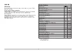
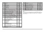
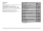
Register Assignment
Range
Default
1
Address
1 – 127
3
2
Minimum speed
0 – 255
7
3
Acceleration delay
0 – 255
4
4
Braking delay
0 – 255
4
5
Maximum speed
0 – 255
230
8
Reset
8
159
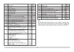
13
Function F1 – F8 with alternative track signal
0 – 255
32
14
Function FL, F9 – F15 with alternative track signal
0 – 255
1
17
Expanded address, higher value byte
192 – 231
192
18
Expanded address, lower value byte
0 – 255
128
19
Multiple unit operation address
0 – 255
0
21
Functions F1 – F8 with multiple unit operation
0 – 255
0
22
Function FL, F9 – F15 with multiple unit operation
0 – 255
0
27
Bit 4: Braking mode voltage against the direction of travel
Bit 5: Braking mode voltage with the direction of travel
0/16
0/32
16
29
Bit 0: Direction normal/inverted
Bit 1: Number of speed levels 14/28(128)
Bit 2: Analog operation off/on
Bit 5: short / long address active
0/1
0/2
0/4
0/32
6
50
Alternative Formats‘
Bit 0: Analog AC
Bit 1: Analog DC
Bit 2: MM
Bit 3: mfx off/on
0/1
0/2
0/4
0/8
14
60
Multi-station announcement
Bit 0 – 3: Number of stations
Bit 4: Last announcement changes the sequence
Bit 5: Locomotive direction changes the sequence
Bit 6: Start for the sequence
0 – 15
0/16
0/32
0/64
36
63
Total volume
0 – 255
240
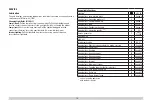
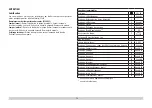
Register Assignment
Range
Default
64
Threshhold for squealing brakes
0 – 255
15
67 – 94 Speed table for speed levels 1 – 28
0 – 255
112
Mapping lights in the front, mode
0 – 21
1
113
Mapping lights in the front, dimmer
0 – 255
255
114
Mapping lights in the front, cycle
0 – 255
20
176
Minimum speed in analog DC
1 – 255
50
177
Maximum speed in analog DC
1 – 255
154
Note:
At www.LGB.de you will find a tool you can use to calculate different decoder set-
tings as well an extensive description of the decoder and the settings. Programming
the decoder settings with the 55015 Universal Hand Controller is also explained in
these instructions.


