3. TECHNICAL BRIEF
- 51 -
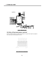
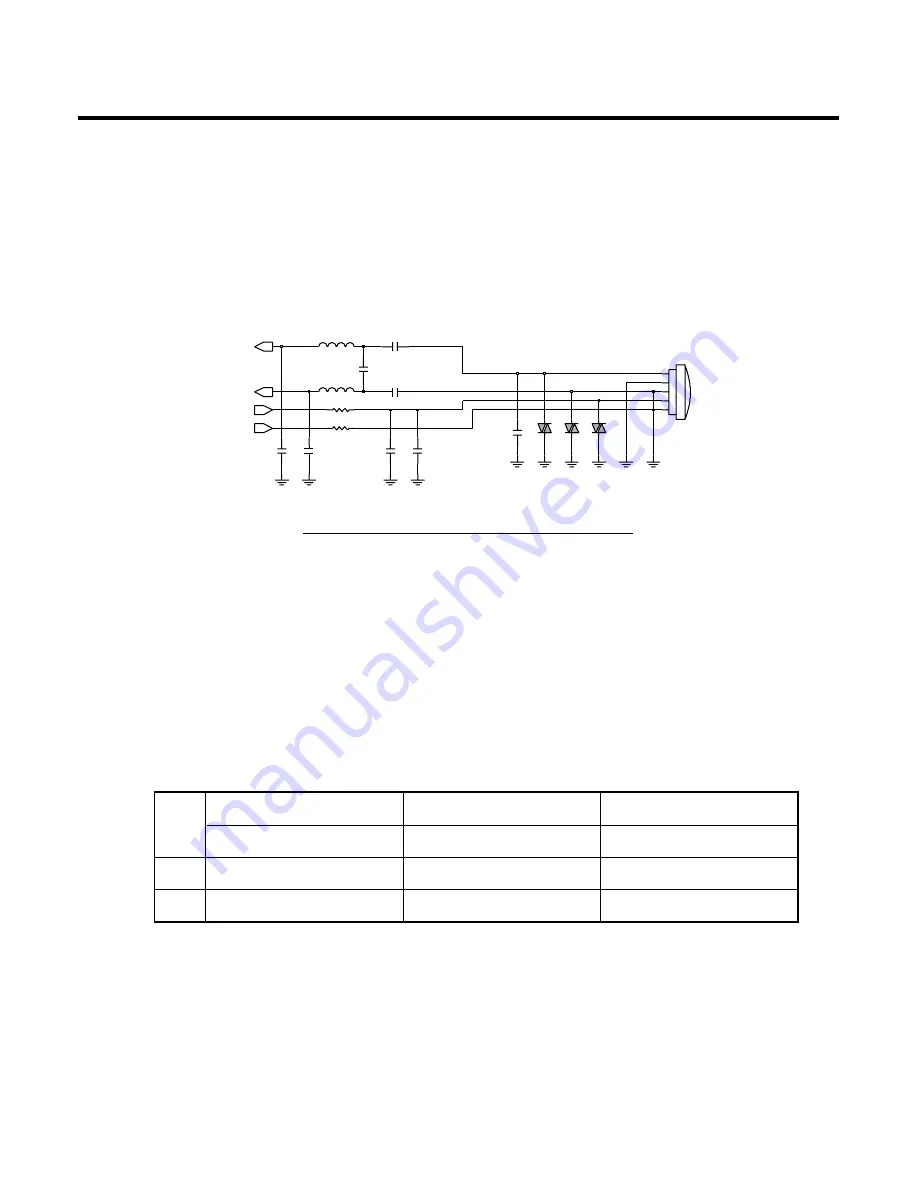
3.13.2. Microphone with gain switching circuit
As controlling the MIC_GAIN_SEL, Microphone sensitivity can be selected both -42dB
(MIC_GAIN_SEL set low) and -30dB(MIC_GAIN_SEL set high)
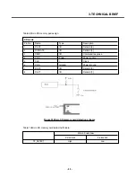
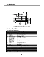
3.14. Multi port switch
Multi port switch has employed to decrease MMI(Multi Media Interface) connector’s pin number. USB,
USART, Remote controlled Headset is connected via this multi port switch. When USB VBUS voltage
is detected Multi port 0 and 1 is connected to USB_DP and USB_DM each. If the remote controlled
headset is plugged into MMI connector, then multi port 0 and 1 in go through REMOTE_INT and
REMOTE_ADC.
Table 8 Multi port switch truth table
Figure 24 Microphone with Gain switching circuit
R122
0
MIC100
SP0102BE3
2
G1
G2
3
G3
5
OUT
1
4
PWR
VA102
VA100
C127
10u
L105
100nH
100p
C117
27p
C114
C125
0.1u
VA101
0
R120
100p
C128
100nH
L104
C116
0.1u
C126
C115
100p
27p
VMICN
MIC1_P
MIC1_N
VMICP
VBUS_USB='L' VBUS_USB='L' VBUS_USB='H'
JACK_DETECT='L' JACK_DETECT='H'
Pin6 REMOTE_INT
TXD
USB_DP
Pin7 REMOTE_ADC
RXD
USB_DM
Содержание KE820
Страница 1: ...Service Manual Model KE820 Service Manual KE820 Date August 2006 Issue 1 0 ...
Страница 3: ... 4 ...
Страница 5: ... 6 ...
Страница 46: ...3 TECHNICAL BRIEF 47 Figure 18 EN SET port control method ...
Страница 69: ...4 PCB layout 70 Figure 45 Main PCB bottom Figure 46 Main PCB bottom placement ...
Страница 70: ...4 PCB layout 71 Figure 47 Sub PCB top Figure 48 Sub PCB top placement ...
Страница 71: ...4 PCB layout 72 Figure 49 Sub PCB bottom Figure 50 Sub PCB bottom placement ...
Страница 114: ...6 Download S W upgrade 115 6 2 Download program user guide ...
Страница 115: ... 116 6 Download S W upgrade ...
Страница 116: ... 117 6 Download S W upgrade ...
Страница 117: ... 118 6 Download S W upgrade ...
Страница 124: ... 125 8 PCB LAYOUT ...
Страница 125: ... 126 8 PCB LAYOUT ...
Страница 126: ... 127 8 PCB LAYOUT ...
Страница 127: ... 128 8 PCB LAYOUT ...
Страница 129: ...9 RF Calibration 130 9 2 3 Click SETTING Menu 9 2 4 Setup Ezlooks menu such as the following figure ...
Страница 131: ...9 RF Calibration 132 9 2 7 Select MODEL 9 2 8 Click START for RF calibration 9 2 9 RF Calibration finishes ...
Страница 132: ...9 RF Calibration 133 9 2 10 Calibration data will be saved to the following folder Saving format year month day_PASS ...
Страница 136: ... 137 11 STANDALONE TEST 4 Click Update Info for communicating Phone and Test Program Connected ...
Страница 141: ... 142 ...
Страница 161: ...Note ...
Страница 162: ...Note ...


