9. RF Calibration
- 131 -
9.2.5. Setup “Line System” menu such as the following figure
9.2.6.Setup Logic operation such as the following figure.
Adiust the number times.
Setup UART Port
PWR: Power Supply
CELL: Call-Test Equipment
Operation Mode
1. By-Pass: not control by GPIB
2. Normal: control by GPIB
Содержание KE820
Страница 1: ...Service Manual Model KE820 Service Manual KE820 Date August 2006 Issue 1 0 ...
Страница 3: ... 4 ...
Страница 5: ... 6 ...
Страница 46: ...3 TECHNICAL BRIEF 47 Figure 18 EN SET port control method ...
Страница 69: ...4 PCB layout 70 Figure 45 Main PCB bottom Figure 46 Main PCB bottom placement ...
Страница 70: ...4 PCB layout 71 Figure 47 Sub PCB top Figure 48 Sub PCB top placement ...
Страница 71: ...4 PCB layout 72 Figure 49 Sub PCB bottom Figure 50 Sub PCB bottom placement ...
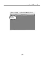
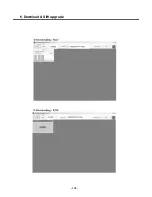
Страница 114: ...6 Download S W upgrade 115 6 2 Download program user guide ...
Страница 115: ... 116 6 Download S W upgrade ...
Страница 116: ... 117 6 Download S W upgrade ...
Страница 117: ... 118 6 Download S W upgrade ...
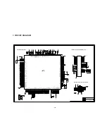
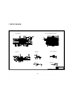
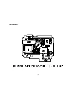
Страница 124: ... 125 8 PCB LAYOUT ...
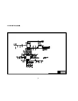
Страница 125: ... 126 8 PCB LAYOUT ...
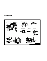
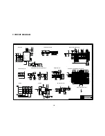
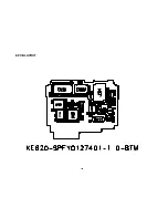
Страница 126: ... 127 8 PCB LAYOUT ...
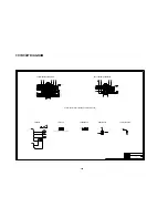
Страница 127: ... 128 8 PCB LAYOUT ...
Страница 129: ...9 RF Calibration 130 9 2 3 Click SETTING Menu 9 2 4 Setup Ezlooks menu such as the following figure ...
Страница 131: ...9 RF Calibration 132 9 2 7 Select MODEL 9 2 8 Click START for RF calibration 9 2 9 RF Calibration finishes ...
Страница 132: ...9 RF Calibration 133 9 2 10 Calibration data will be saved to the following folder Saving format year month day_PASS ...
Страница 136: ... 137 11 STANDALONE TEST 4 Click Update Info for communicating Phone and Test Program Connected ...
Страница 141: ... 142 ...
Страница 161: ...Note ...
Страница 162: ...Note ...

