3. TECHNICAL BRIEF
- 45 -
3.11 Battery current consumption monitor
KE770use a current monitoring function to calculate the battery capacity and the remaining time, as
monitoring current flow from the battery thru 47mohm resistor.
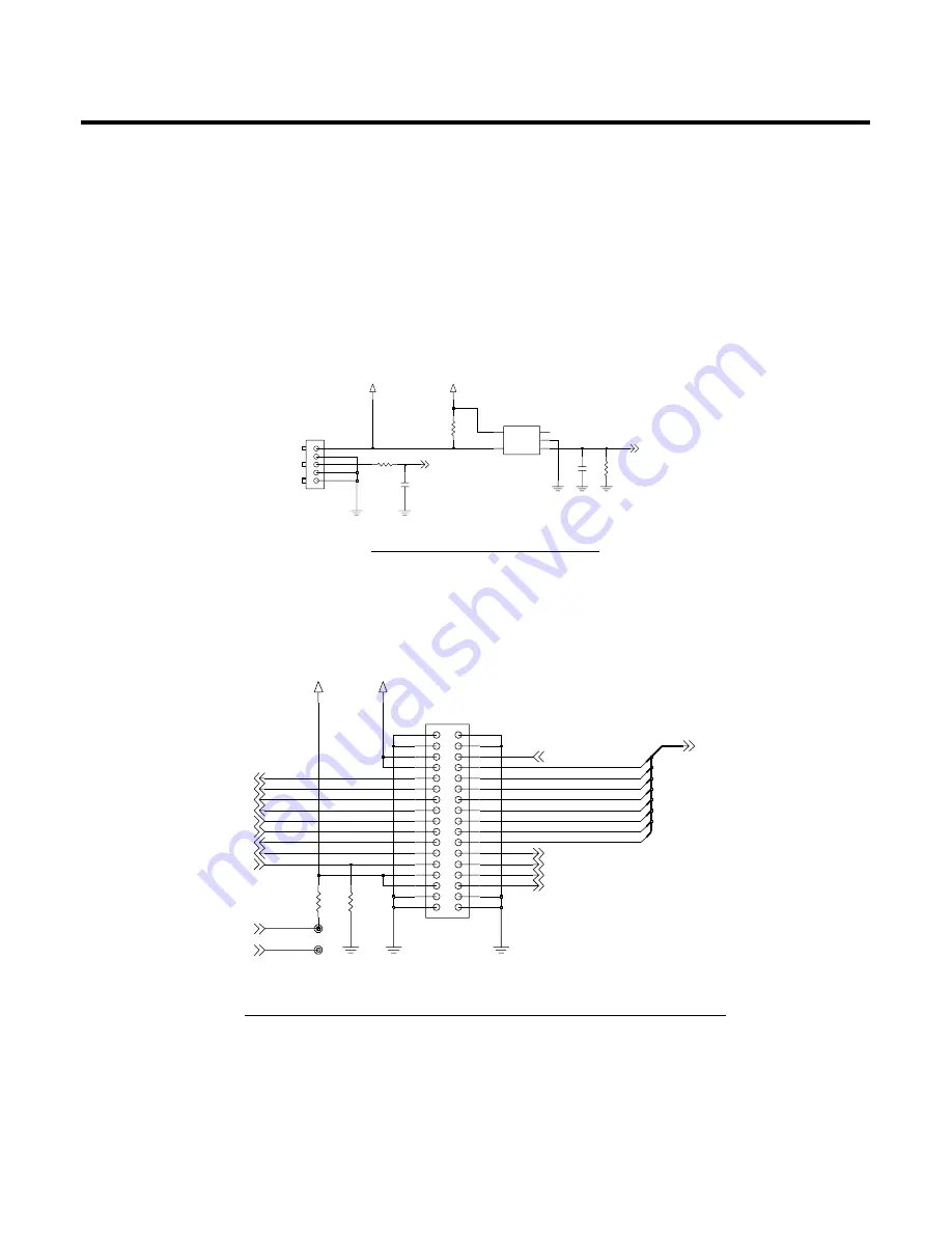
3.12 JTAG & ETM interface connector
In case of KE770mass production, the JTAG & ETM interface connector will not be mount on board.
That is only for developing and software debugging purpose.( It will not be mounted on mass
production PCB)
(1%)
(1%)
BATTERY CURRENT MONITOR
(47 milli Ohm)
VSUPPLY
2.2K
R209
R207
1K
GND
2
3
IOUT
LOAD
5
1
NC
VIN
4
U201
ZXCT1010E5TA
R204
47mohm
C204
1u
VBAT
CN201
G1
G2
1
2
3
C213
27p
BATT_TEMP
I_MONITOR
Figure 15 Current monitor circuit
TP114
TP115
1V8_MEM
G3
G4
R126
NA
26
27
28
29
30
17
18
19
20
21
22
23
24
G1
G2
10
11
12
13
14
15
2
3
4
5
6
7
8
9
16
25
CN101
1
NA
R127
2V72_IO
TRACEPKT(1)
TRACEPKT(2)
TRACEPKT(3)
TRIG_OUT
_TRST
TDI
TMS
TCK
RTCK
TDO
_EXTRST
TRIG_IN
TRACEPKT(7)
TRACEPKT(0:7)
MON1
MON2
TRACEPKT(4)
TRACEPKT(5)
TRACEPKT(6)
TRACECLK
TRACESYNC
PIPESTAT0
PIPESTAT1
PIPESTAT2
TRACEPKT(0)
Figure 16 JTAG & ETM(Embedded Trace Module) interface connector
Содержание KE 770
Страница 1: ...Service Manual Model KE770 Service Manual KE770 Date April 2007 Issue 1 0 ...
Страница 3: ... 4 ...
Страница 5: ... 6 ...
Страница 49: ...3 TECHNICAL BRIEF 50 3 15 BLUETOOTH Figure 22 BLUETOOTH Functional block diagram ...
Страница 57: ...3 TECHNICAL BRIEF 58 RF Block Diagram III 2 RF circuit ...
Страница 76: ...Check Points 5 Trouble shooting 77 ...
Страница 78: ...5 Trouble shooting 79 ...
Страница 82: ...5 Trouble shooting 83 ...
Страница 87: ...5 Trouble shooting 88 ...
Страница 100: ... 101 6 Download S W upgrade Click on the blue text to select the COM port ...
Страница 101: ...6 Download S W upgrade 102 Will change the window as below ...
Страница 103: ...6 Download S W upgrade 104 During download the screen will look something like this ...
Страница 105: ... 106 ...
Страница 111: ... 112 8 PCB LAYOUT ...
Страница 112: ... 113 8 PCB LAYOUT ...
Страница 113: ... 114 8 PCB LAYOUT ...
Страница 114: ... 115 8 PCB LAYOUT ...
Страница 115: ... 116 8 PCB LAYOUT ...
Страница 117: ...9 RF Calibration 118 9 2 3 Click SETTING Menu 9 2 4 Setup Ezlooks menu such as the following figure ...
Страница 119: ...9 RF Calibration 120 9 2 7 Select MODEL 9 2 8 Click START for RF calibration 9 2 9 RF Calibration finishes ...
Страница 121: ...10 Stand alone Test 122 4 Click Update Info for communicating Phone and Test Program ...
Страница 125: ... 126 ...
Страница 143: ...Note ...
Страница 144: ...Note ...


