3.4. Power ON/OFF
KE770Power State : Defined 3cases as follow
]
Power-ON : Power key detect ( SM-Power’s ON port
]
Power-ON-charging : Charger detect.
]
Power-ON-remote : remote power on detect (Factory use only)
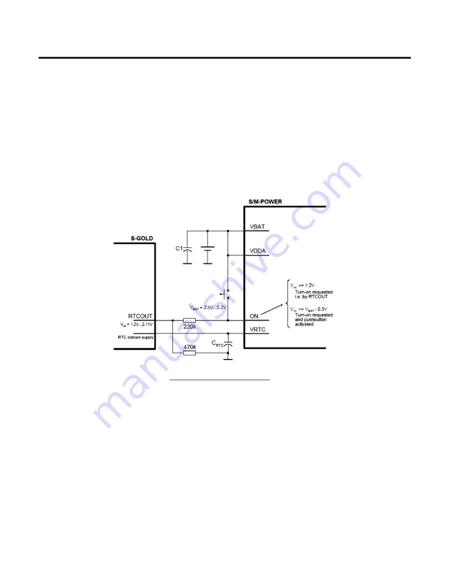
Input ON is a power-on input for SM-POWER with 2 active high levels (see Figure 8). It might be
triggered by a push button or by the RTCOUT output of the S-GOLD device as well. To detect if the
push-button is pressed during system operation the logical level at pin ON or its change (if Bit 1 EION
in INTCTRL2 is asserted) is recorded in bit LON of the ISF register. If the high level of voltage at pin
ON does not reach V
IHdet
(Vbat-0.8 ~ Vbat-0.3) the above-mentioned bit won’t be set.
To support Remote power on function for factory mass production, applied an analog switch as
following figure. As monitoring the RPWRON(GPIO_110) and Key matrix KP_OUT(1) & KP_IN(5),
KE770system recognize whether remote power on or End-key pushed
3. TECHNICAL BRIEF
- 38 -
Figure 7 Power on application.
Содержание KE 770
Страница 1: ...Service Manual Model KE770 Service Manual KE770 Date April 2007 Issue 1 0 ...
Страница 3: ... 4 ...
Страница 5: ... 6 ...
Страница 49: ...3 TECHNICAL BRIEF 50 3 15 BLUETOOTH Figure 22 BLUETOOTH Functional block diagram ...
Страница 57: ...3 TECHNICAL BRIEF 58 RF Block Diagram III 2 RF circuit ...
Страница 76: ...Check Points 5 Trouble shooting 77 ...
Страница 78: ...5 Trouble shooting 79 ...
Страница 82: ...5 Trouble shooting 83 ...
Страница 87: ...5 Trouble shooting 88 ...
Страница 100: ... 101 6 Download S W upgrade Click on the blue text to select the COM port ...
Страница 101: ...6 Download S W upgrade 102 Will change the window as below ...
Страница 103: ...6 Download S W upgrade 104 During download the screen will look something like this ...
Страница 105: ... 106 ...
Страница 111: ... 112 8 PCB LAYOUT ...
Страница 112: ... 113 8 PCB LAYOUT ...
Страница 113: ... 114 8 PCB LAYOUT ...
Страница 114: ... 115 8 PCB LAYOUT ...
Страница 115: ... 116 8 PCB LAYOUT ...
Страница 117: ...9 RF Calibration 118 9 2 3 Click SETTING Menu 9 2 4 Setup Ezlooks menu such as the following figure ...
Страница 119: ...9 RF Calibration 120 9 2 7 Select MODEL 9 2 8 Click START for RF calibration 9 2 9 RF Calibration finishes ...
Страница 121: ...10 Stand alone Test 122 4 Click Update Info for communicating Phone and Test Program ...
Страница 125: ... 126 ...
Страница 143: ...Note ...
Страница 144: ...Note ...


