


49
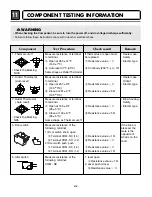
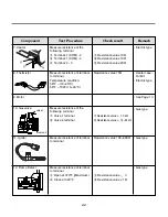
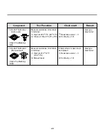
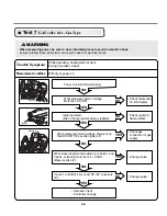
Trouble Symptom
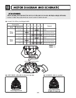
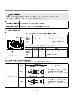
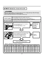
2. Status Mode Of The Connection
1.Power Connection
Measurement Condition
Check the Tab Relays Connection properly.
With Dryer Power On; Connector linked to Controller.
Tab Relay 1
Tab Relay 1
Trans
Tab Relay 1
Tab Relay 2
k
r
a
m
e
R
r
e
n
r
u
B
High
Mid High
Medium
High
Mid High
Medium
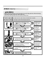
Temperature Control below 68
±
4°C.
Turn on Heater1 and Heater2.
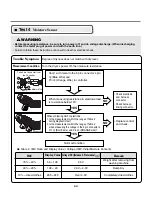
Temperature Control below 70
±
4°C.
Turn on Burner
Temperature Control below 47
±
4°C.
Turn on Burner
Temperature Control below 52
±
4°C.
Only Turn on Heater1.
on
on
O
O
O
O
on
off
off
on
on
on
Low
Extra Low
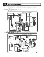
PCB ASSEMBLY LAYOUT
Low
Extra Low
Tab Relay 2
Heater 1
Heater 2
Remark
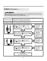
Connector Housing
Black
Check the matching color between
harness wire and tab relay.
(Black Housing – Black Tab Relay)
Check the matching color between
harness wire and tab relay.
(White Housing – White Tab Relay)
White
Color
Table1 : Connection of the Tab Relay with Heater (Electric)
Table 2 : Connection of the Tab Relay with Burner (Gas)
Table1 : Connection of Tab Relay with the Tab Relay of the PCB ASSEMBLY (Electric)
Harness
Connection
Remark
PCB
1
2
Yellow Wire
Black Wire
Connector Housing
Tap relay 1
Tap relay 2
1
2
Blue Wire
Black Wire
Connector Housing
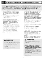
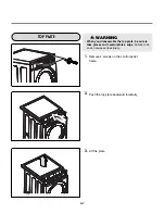
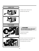
WARNING
• When measuring power, be sure to wear insulated gloves, to and avoid an electric shock.
• Failure to follow these instructions can result in death or electrical shock.
!
LG Electronics Inc.
6870EC9244D (GIANT(D)-PJT)
100203 KMK (A:HOR)
BLACK
WHITE
COM
SV1
SV2
N
TS
FLAME
E-SUDS
CARD
COIN
MOTOR
DOOR
R405
+
-
~
~
BD200
+
-
~
~
BD1
C44
C48
SMPS
CRT
C202
YL2
CE91
NA6
R454
IC71
RY200
C1
D2
D200
D201
D202
D203
D204
CE200
D401
BL2
BL3
BL4
PIN1
PIN2
PIN3
ZD1
ZD2
ZD3
ZD4
FL
R101
R103
R104
D41
D42
C101
C103
C104
CE1
CE2
CE3
CE4
CE5
D55
IC2
D56
R351
R18
R2
R3
R5
R6
R7
R8
ZD200
D101
D103
Q200
D104
Q201
R57
Z41
Z42
BUZZER
X2
X4
X5
DOWNLOAD
D351
D352
R203
R205
R206
R207
R209
C50
C2
Pb
F1
C7
Содержание / GD1329QES
Страница 2: ...MARCH 2010 PRINTED IN KOREA P No MFL62119919 ...
Страница 46: ...13 CONTROL LAY OUT 45 PWB ASSEMBLY DISPLAY LAY OUT PWB ASSEMBLY LAY OUT ...
Страница 69: ...EXPLODED VIEW 19 19 1 1 Control Panel Plate Assembly Coin Type A210 A120 A110 68 ...
Страница 70: ...19 1 2 Control Panel Plate Assembly Card Type A210 A120 A117 A110 69 ...