62
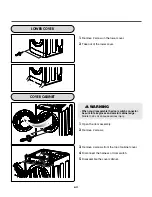
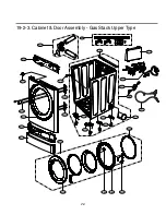
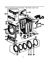
LOWER COVER
1.
Remove 2 screw on the lower cover.
2.
Take out of the lower cover.
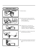
COVER CABINET
1.
Open the door assembly.
2.
Remove 2 screws.
3.
Remove 4 screws from the top of cabinet cover.
4.
Disconnect the harness of door switch.
5.
Disassemble the cover cabinet.
WARNING
• When you disassemble the door switch connector,
be sure to take gloves and careful cabinet edge.
Failure to do so can cause serious injury.
!
Содержание / GD1329QES
Страница 2: ...MARCH 2010 PRINTED IN KOREA P No MFL62119919 ...
Страница 46: ...13 CONTROL LAY OUT 45 PWB ASSEMBLY DISPLAY LAY OUT PWB ASSEMBLY LAY OUT ...
Страница 69: ...EXPLODED VIEW 19 19 1 1 Control Panel Plate Assembly Coin Type A210 A120 A110 68 ...
Страница 70: ...19 1 2 Control Panel Plate Assembly Card Type A210 A120 A117 A110 69 ...

