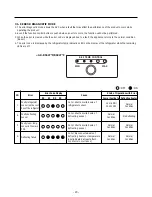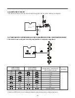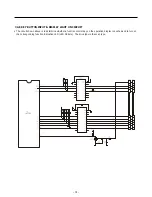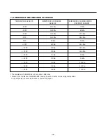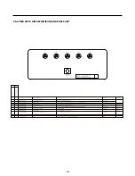
7-1-10 TEST MODE
1. The test mode allows checking the PCB and the function of the product as well as finding out the defective part in case of
an error.
2. The test button is on the main PCB of the refrigerator (Test S/W). The test mode will be cleared in 5 minutes on test
mode 1 and in 2 hours on test mode 2 and then reset.
3. While in the test mode, the function control button is not recognized though the recognition tone (beep~) sounds.
4. After exiting the test mode, be sure reset by unplugging and then plugging in the appliance.
5. If an error, such as a sensor failure, is detected while in the test mode, the test mode is cleared and the error code is displayed.
6. While an error code is displayed, the test mode will not be activated even if the test button is pushed.
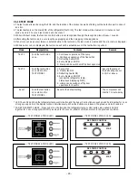
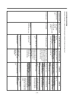
Mode
Manipulation
Contents
Remark
TEST 1
Push the test button
1. Continuous operation of the comp
once.
2. Continuous operation of the freezer fan
3. Defrosting heater OFF
4. Every display LED ON
5. F-lamp can be switch on/off by door open close
TEST 2
Push the test button
1. Comp OFF
Reset if the temp of
once while in the
2. Freezer fan OFF
the defrosting sensor
TEST MODE 1.
3. Defrosting heater ON
is 13¡C or above.
4. Every display LED OFF
(except the refrigerator temp.
status keys displaying Ô2Õ)
5. H-lamp can be switch on-off by door
open/close for 5 secÕs
Reset
Push the test button
Reset to the default setting
The compressor will
once while in the
start in 7 minute-delay.
TEST MODE 2.
- 24 -
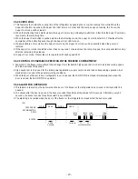
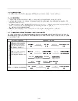
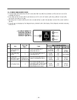
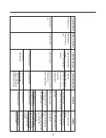
* LED Check Mode: When the refrigerator temp control button and the Super Cool button are pushed and held together for 1 sec
or longer, every LED on the display turns on simultaneously. When the buttons are released, the previous mode is restored.
* FAN RPM VARIETY CHECK : Press super cool button and the refrigerator temp control button are pushed and held
together for 1 sec or longer, FAN RPM is reversed for 30 second (HIGH
Ö
LOW) and return to the previous condition.
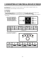
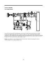
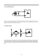
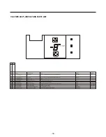
<TEST MODE2 STATUS LED>
<TEST MODE1 STATUS LED>
MIN
MAX
REF. TEMP. CONTROL
MIN
MAX
REF. TEMP. CONTROL
<TEST MODE2 STATUS LED>
<TEST MODE1 STATUS LED>
Содержание B712Y*B
Страница 36: ...7 5 2 REPLACEMENT PARTS LIST 36 ...
Страница 37: ... 37 ...
Страница 38: ...7 5 3 PWB ASS Y DISPLAY AND PARTS LIST 38 ...
Страница 39: ... 39 7 5 4 PWB ASS Y DISPLAY I MICOM AND PARTS LIST ...
Страница 40: ... 40 7 5 5 V LED DISPLAY PART LIST ...
Страница 41: ...7 6 PWB DIAGRAM 41 ...
Страница 42: ... 42 ...
Страница 44: ... 44 149D 155J 149B 120 118 119 138 120 110 111 149B 405A 140A 133 405C 405C 404A ...
Страница 45: ... 45 101 122 241D 244C 244A 162 212C 212A 205A 241A 279A 123 102 241C 235A 205A 210A 173 172 241E ...
Страница 46: ...P No MFL38971701 MAR 2007 Printed in Korea ...

