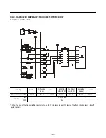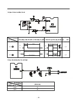
- 13 -
6. TROUBLESHOOTING
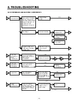
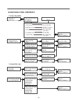
6-1 COMPRESSOR AND ELECTRIC COMPONENTS
1
2
3
4
5
2
5
5
3
5
4
5
5
1
4
3
YES
YES
YES
YES
NO
NO
YES
YES
YES
NO
NO
NO
Power Source.
Remove the PTC-Starter
from the Compressor
and measure the voltage
between Terminal C of
Compressor and
Terminals 5 or 6 of PTC.
No Voltage.
(Rating Voltage
–10%)?
Replace OLP.
Reconnect.
Replace
PTC-Starter.
Replace OLP.
O.K.
Check connection
condition.
OLP disconnected?
Advise the customer
to use a regular
Trans.
Replace Compressor.
OLP works within
30 sec. in forcible
OLP operation by
turning instant power
on and off.
Components start at
voltage –10% of
rated voltage.
Applied voltage isn’t
in the range of Rating
Voltage –10%.
Check the resistance
among M-C, S-C and
M-S in Motor
Compressor.
Check the resistance
of two terminals in
PTC-Starter.
Check if applying
a regular OLP.
Measure minimum
starting voltage after 5
min. for balancing cycle
pressure and cooling
the PTC.
Check the
resistance of
Motor
Compressor.
Check the
resistance of
PTC-Starter.
Check OLP.
Check
starting state.
Содержание B712Y*B
Страница 36: ...7 5 2 REPLACEMENT PARTS LIST 36 ...
Страница 37: ... 37 ...
Страница 38: ...7 5 3 PWB ASS Y DISPLAY AND PARTS LIST 38 ...
Страница 39: ... 39 7 5 4 PWB ASS Y DISPLAY I MICOM AND PARTS LIST ...
Страница 40: ... 40 7 5 5 V LED DISPLAY PART LIST ...
Страница 41: ...7 6 PWB DIAGRAM 41 ...
Страница 42: ... 42 ...
Страница 44: ... 44 149D 155J 149B 120 118 119 138 120 110 111 149B 405A 140A 133 405C 405C 404A ...
Страница 45: ... 45 101 122 241D 244C 244A 162 212C 212A 205A 241A 279A 123 102 241C 235A 205A 210A 173 172 241E ...
Страница 46: ...P No MFL38971701 MAR 2007 Printed in Korea ...


