


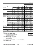


- 183 -
Copyright ©2009 LG Electronics. Inc. All right reserved.
Only for training and service purposes
LGE Internal Use Only
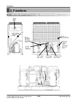
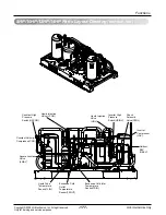
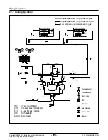
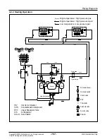
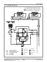
4. Piping Diagrams
4.1.1 Cooling Operation
INV
: Inverter compressor
EEV : Linear Expansion Valve
O/S
: Oil Separator
Accum. : Accumulator
:High temperature / High pressure liquid
:High temperature / High pressure gas
:Low temperature / Low pressure gas
Heat Exchanger
Fan
lndoor unit
EEV
Filter
Filter
Heat Exchanger
Fan
lndoor unit
EEV
Filter
Filter
H/G
IM FAN
Gas pipe
Liquid pipe
Accum.
O/S
Liquid Injection
INV
Pressure sensor
Pressure switch
Check valve
EEV
Thermistor
Solenoid valve
Service valve
Strainer
S
S
S
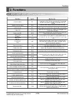
4.1 Refrigerant Flow for Each Operation Mode
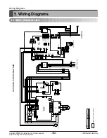
Piping Diagrams