ARIA SOHO Hardware Description and Installation Manual
Issue 1
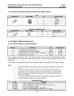
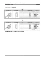
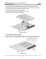
BOARD INSTALLATION
Aug, 2006
27
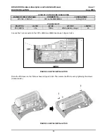
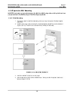
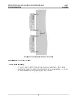
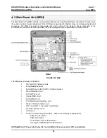
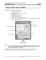
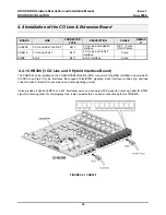
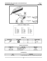
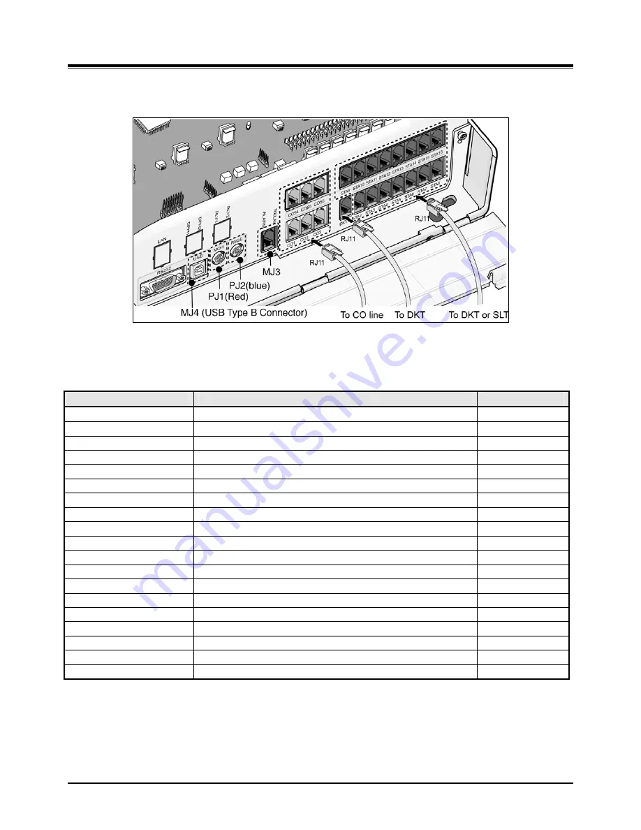
The MBU is installed in the KSU and provides various kinds of connectors RJ11 modular jacks for the connection of
peripheral boards and miscellaneous functions (refer to Figure and Table).
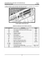
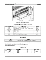
FIGURE 4.2B MBU CONNECTION PORTS
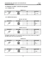
CONNECTOR, MODULAR JACK AND SWITCH FUNCTIONS
SWITCH/CONNECTOR
FUNCTIONS
REMARK
CN1
KSU Connection to Expansion KSU with Flat cable
50Pins
CN2
CO and Extension Board(CHB308/CSB316/SLIB8) installation
50Pins
CN3 LANU
Installation
32Pins
CN4 MODU
Installation
20Pins
CN5 VMIU/AAFU
Installation
32Pins
CN9 & CN10
CMU50PR Installation
6 & 8Pins
CN13 DPU2
Installation
16Pins
CN6
JTAG Port for Emulator
For Test
CN7
PSU Connection (+5V, -5V, +30V)
7Pins
CN8
RS-232C Port Connection
9Pins
MJ1
3 CO Lines Connection
3Arrays
MJ2
8 DKTs or 1 DKT and 7 SLTs Connection
8Arrays
MJ3
Alarm Sensor and External Relay Contact
1Array
MJ4
USB Connection(USB Type B Connector)
Slave Mode
PJ1 (Red)
External MOH Connection
PJ2 (Blue)
External PAGE Connection
SW1
4 Poles DIP Switch for Software Usage
Default = All ON
SW2
Lithium Battery ON/OFF Switch for Memory and RTC Back Up
Default = OFF
SW3
System Reset Button


