3 Description
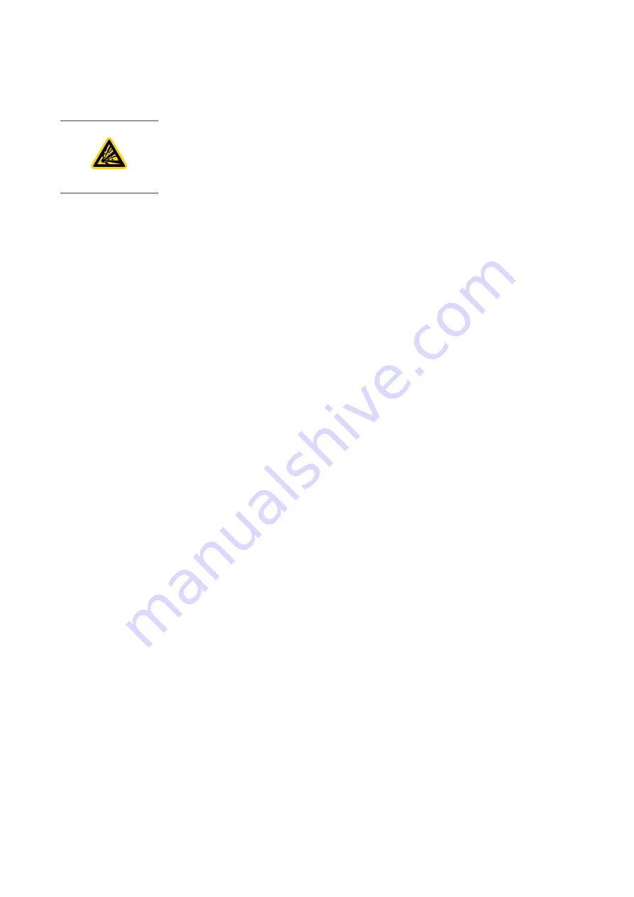
WARNING: EXPLOSION HAZARD
Risk of injury and damage to the equipment. The pump must not be installed and
operated within explosion hazard areas.
The TRIVAC L pumps are two-stage, oil sealed, sliding-vane vacuum
pumps.
The pump is designed for pumping inert gases in the range of medium
vacuum, between atmospheric pressure and the ultimate pressure of the
pump. When removing condensable vapours, a gas ballast valve must be
opened.
TRIVAC L pumps are capable of pumping gases, vapours and evacuating
vessels or vacuum systems down into the medium vacuum range. The
standard version of the pump is not suitable for pumping oxygen exceeding
25% and for pumping hazardous substances or aggressive or corrosive
gases.
Through an intermediate flange, a four-pole three-phase motor is mounted
to the coupling housing. The pump and motor shafts are directly connected
by a flexible coupling. The oil-level glass, drain valve and nameplate are
arranged on the same side. All vacuum connections are default on the top of
the pump.
3.1 Principle of operation
The pump is an oil-sealed rotary vane pump. The anti-suck back valve, gas
ballast valve and oil return circuit are integrated functional elements. The
pump is driven by a directly flanged motor.
The rotor, mounted eccentrically in the pump housing, has two radially
sliding vanes which divide the pump chamber into several compartments.
The volume of each compartment changes periodically with the rotation of
the rotor.
As a result, gas is sucked in at the intake port. The gas passes through a
dirt trap sieve and open the anti-suck back valve, then enters the pump
chamber. In the pump chamber, the gas is passed on and compressed after
the inlet aperture is closed by the vane.
The oil injected into the pump chamber is used for sealing and lubricating.
The slap noise of the oil in the pump which usually occurs when attaining
the ultimate pressure is prevented by admitting a very small amount of air
into the pump chamber.
The compressed gas in the pump chamber is ejected through the exhaust
valve. The oil entrained in the gas is coarsely separated by the exhaust
cover. There the oil is also freed of mechanical impurities. The gas leaves the
pump through the exhaust port.
During compression, a controlled amount of air – the so-called gas ballast –
can be allowed to enter the pump chamber by opening the gas ballast
valve. The gas ballast stops the condensation of vapours in the pump
chamber up to the limit of the water vapour tolerance as specified in the
technical data for the pump.
The gas ballast valve is opened (position I and position II) and closed
(position 0) by turning the gas ballast knob on the front.
13
300956027_002_A0 - 03/2022 - © Leybold
Description
Содержание 1019040V00
Страница 62: ...This page has been intentionally left blank ...
Страница 63: ...This page has been intentionally left blank ...


