


4-62
Service Manual
7510
Go Back
Previous
Next
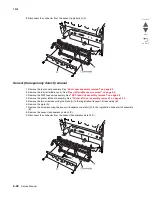
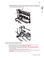
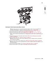
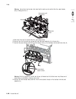
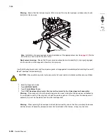
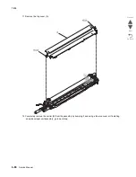
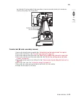
Replacement note:
When replacing the developer interlock plate assembly (A), install the bottom edge
first and ensure that all four developer unit assemblies are properly aligned when replacing the developer
interlock plate assembly (A).
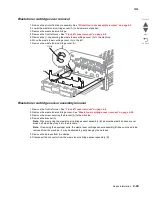
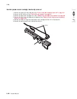
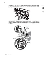
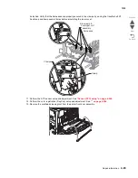
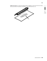
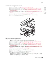
Replacement warning:
Ensure that the erase lamp harnesses and developer unit assembly harnesses
are correctly installed in the clamps, or they may become detached. Verify that the harnesses are properly
secured in the clamps by moving the transfer belt lift handle up and down several times before reinstalling
the inner cover.
Clamp
Erase lamp &
developer unit
assembly
harnesses
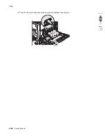
Clamps
Содержание X945E
Страница 20: ...xx Service Manual 7510 Go Back Previous Next ...
Страница 25: ...Notices and safety information xxv 7510 Go Back Previous Next ...
Страница 26: ...xxvi Service Manual 7510 Go Back Previous Next ...
Страница 32: ...xxxii Service Manual 7510 Go Back Previous Next ...
Страница 88: ...1 56 Service Manual 7510 Go Back Previous Next TTM theory ...
Страница 97: ...General information 1 65 7510 Go Back Previous Next 3TM theory ...
Страница 104: ...1 72 Service Manual 7510 Go Back Previous Next 1TM theory ...
Страница 111: ...General information 1 79 7510 Go Back Previous Next Duplex ...
Страница 416: ...3 36 Service Manual 7510 Go Back Previous Next Exiting Configuration Menu See Exiting Configuration Menu on page 3 50 ...
Страница 432: ...3 52 Service Manual 7510 Go Back Previous Next ...
Страница 465: ...Repair information 4 33 7510 Go Back Previous Next 4 Remove the media out actuator A Front Bosses Lower view A ...
Страница 475: ...Repair information 4 43 7510 Go Back Previous Next E F ...
Страница 483: ...Repair information 4 51 7510 Go Back Previous Next Connectors A ...
Страница 506: ...4 74 Service Manual 7510 Go Back Previous Next 9 Remove the transfer belt lift latch assembly A A ...
Страница 567: ...Repair information 4 135 7510 Go Back Previous Next 7 Remove the scanner PS cooling fan assembly A Connector A ...
Страница 608: ...4 176 Service Manual 7510 Go Back Previous Next 8 Remove the shafts D 9 Remove the tray support rolls B ...
Страница 623: ...Repair information 4 191 7510 Go Back Previous Next ...
Страница 626: ...4 194 Service Manual 7510 Go Back Previous Next 8 Remove the media feed lift motor B A B Connector Rear ...
Страница 643: ...Repair information 4 211 7510 Go Back Previous Next 4 Remove the tray module drive motor A A Connector ...
Страница 653: ...Repair information 4 221 7510 Go Back Previous Next ...
Страница 714: ...4 282 Service Manual 7510 Go Back Previous Next ...
Страница 715: ...Connector locations 5 1 7510 Go Back Previous Next 5 Connector locations Locations ...
Страница 720: ...5 6 Service Manual 7510 Go Back Previous Next Printhead Polygon mirror motor ...
Страница 725: ...Connector locations 5 11 7510 Go Back Previous Next ...
Страница 726: ...5 12 Service Manual 7510 Go Back Previous Next ...
Страница 729: ...Connector locations 5 15 7510 Go Back Previous Next Switch media size Switch TTM media size ...
Страница 730: ...5 16 Service Manual 7510 Go Back Previous Next Media feed unit assembly Sensor tray 4 feed out ...
Страница 743: ...Parts catalog 7 9 7510 Go Back Previous Next Assembly 8 Media feed unit 3 11 13 5 9 2 10 6 4 12 1 8 6 7 14 ...
Страница 765: ...Parts catalog 7 31 7510 Go Back Previous Next Assembly 29 Electrical 1 3 5 9 2 10 6 4 8 1 7 ...
Страница 768: ...7 34 MFP Service Manual 7510 Go Back Previous Next Assembly 31 Electrical 3 8 9 2 3 7 10 1 5 6 4 ...
Страница 770: ...7 36 MFP Service Manual 7510 Go Back Previous Next Assembly 32 Electrical 4 2 1 4 3 5 7 6 8 9 ...
Страница 774: ...7 40 MFP Service Manual 7510 Go Back Previous Next Assembly 35 ADF base 10 1 3 7 5 9 2 6 4 8 Front ...
Страница 776: ...7 42 MFP Service Manual 7510 Go Back Previous Next Assembly 36 ADF feeder 3 13 7 5 2 12 6 4 8 1 11 10 9 ...
Страница 780: ...7 46 MFP Service Manual 7510 Go Back Previous Next Assembly 38 ADF media guide 3 10 5 9 2 6 8 1 4 7 10 11 12 ...
Страница 787: ...Parts catalog 7 53 7510 Go Back Previous Next Assembly 43 CCD lens assembly 3 11 5 8 2 9 6 4 7 1 10 ...
Страница 792: ...7 58 MFP Service Manual 7510 Go Back Previous Next Assembly 46 Scanner optics 3 7 5 2 6 4 1 2 2 2 1 2 2 ...
Страница 797: ...Parts catalog 7 63 7510 Go Back Previous Next Assembly 50 1TM feed unit assembly 4 3 5 4 1 2 ...
Страница 799: ...Parts catalog 7 65 7510 Go Back Previous Next Assembly 51 1TM media feed unit 3 11 13 5 9 2 10 6 4 12 1 8 6 7 14 ...
Страница 802: ...7 68 MFP Service Manual 7510 Go Back Previous Next Assembly 53 1TM drive and electrical ...
Страница 804: ...7 70 MFP Service Manual 7510 Go Back Previous Next Assembly 54 3TM covers 3 5 2 4 1 ...
Страница 806: ...7 72 MFP Service Manual 7510 Go Back Previous Next Assembly 55 3TM feed unit assembly 4 3 5 4 1 2 4 4 ...
Страница 808: ...7 74 MFP Service Manual 7510 Go Back Previous Next Assembly 56 3TM media feed unit 3 11 13 5 9 2 10 6 4 12 1 8 6 7 14 ...
Страница 810: ...7 76 MFP Service Manual 7510 Go Back Previous Next Assembly 57 3TM left door 5 8 6 1 2 3 7 4 8 4 9 9 9 ...
Страница 812: ...7 78 MFP Service Manual 7510 Go Back Previous Next Assembly 58 3TM drive and electrical ...
Страница 815: ...Parts catalog 7 81 7510 Go Back Previous Next Assembly 60 TTM media trays 3 5 4 3 7 2 6 8 1 ...
Страница 817: ...Parts catalog 7 83 7510 Go Back Previous Next Assembly 61 TTM media tray 3 3 7 5 2 6 1 5 9 8 4 4 3 ...
Страница 824: ...7 90 MFP Service Manual 7510 Go Back Previous Next Assembly 67 TTM drive and electrical ...
Страница 828: ...7 94 MFP Service Manual 7510 Go Back Previous Next ...
Страница 836: ...I 8 Service Manual 7510 Go Back Previous Next ...
Страница 844: ...I 16 Service Manual 7510 Go Back Previous Next ...


