


3-20
Service Manual
7510
Go Back
Previous
Next
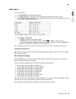
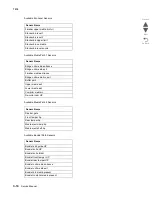
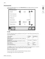
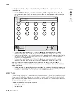
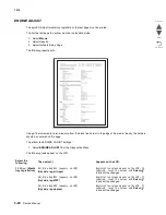
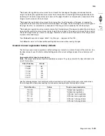
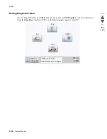
The Configuration ID setting allows you to set both Configuration IDs simultaneously. To set one or both
Configuration IDs:
1.
From the PRINTER SETUP menu, touch the icon to the right of the Configuration ID menu item. The
screen displays the value of both Configuration IDs. By default, the cursor appears on the Configuration
ID 1 line.
2.
To change the value of Configuration ID 1, touch the
Backspace
key to erase any of the existing
characters. Then enter the correct ID using the number and letter keys that appear on the screen.
3.
To edit the value of Configuration ID 2, touch a section of the display screen that appears inside of the text
box containing the current value of Configuration ID 2. The cursor appears in the text box containing the
current value of Configuration ID 2.
4.
To change the value of Configuration ID 2, touch the
Backspace
key to erase any of the existing
characters. Then enter the correct ID using the number and letter keys that appear on the screen.
Note:
To exit the Configuration ID screen and return to the PRINTER SETUP menu, touch
Back
.
Note:
Although it is recommended that all unused and reserved bits be set to zero, the code will not validate or
enforce this condition.
5.
To save the values of both Configuration IDs, touch
Submit
. The printer validates both IDs. If either ID is
invalid, the printer posts
Invalid ID
, discards any changes, and displays the original Configuration IDs. If
both IDs are valid, the printer automatically returns to the PRINTER SETUP menu.
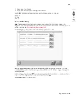
EVENT LOG
The exact number of events recorded in the Event Log will vary since each event requires a different amount of
storage space. When the Event Log requires more space to record an event, it overwrites the oldest currently
logged event(s) and inserts the new event into the first log position. Consecutive log entries may be identical if
the same event occurred twice in a row.
The Event Log records the following types of events:
•
All 9xx Service Errors
•
2xx Paper Jams
vga
?
Back
Submit
CC 00 01 81
B0 55 70 0C
Config ID1
Config ID2
1
2
3
4
5
6
7
8
9
0
a
b
c
d
e
f
Содержание X945E
Страница 20: ...xx Service Manual 7510 Go Back Previous Next ...
Страница 25: ...Notices and safety information xxv 7510 Go Back Previous Next ...
Страница 26: ...xxvi Service Manual 7510 Go Back Previous Next ...
Страница 32: ...xxxii Service Manual 7510 Go Back Previous Next ...
Страница 88: ...1 56 Service Manual 7510 Go Back Previous Next TTM theory ...
Страница 97: ...General information 1 65 7510 Go Back Previous Next 3TM theory ...
Страница 104: ...1 72 Service Manual 7510 Go Back Previous Next 1TM theory ...
Страница 111: ...General information 1 79 7510 Go Back Previous Next Duplex ...
Страница 416: ...3 36 Service Manual 7510 Go Back Previous Next Exiting Configuration Menu See Exiting Configuration Menu on page 3 50 ...
Страница 432: ...3 52 Service Manual 7510 Go Back Previous Next ...
Страница 465: ...Repair information 4 33 7510 Go Back Previous Next 4 Remove the media out actuator A Front Bosses Lower view A ...
Страница 475: ...Repair information 4 43 7510 Go Back Previous Next E F ...
Страница 483: ...Repair information 4 51 7510 Go Back Previous Next Connectors A ...
Страница 506: ...4 74 Service Manual 7510 Go Back Previous Next 9 Remove the transfer belt lift latch assembly A A ...
Страница 567: ...Repair information 4 135 7510 Go Back Previous Next 7 Remove the scanner PS cooling fan assembly A Connector A ...
Страница 608: ...4 176 Service Manual 7510 Go Back Previous Next 8 Remove the shafts D 9 Remove the tray support rolls B ...
Страница 623: ...Repair information 4 191 7510 Go Back Previous Next ...
Страница 626: ...4 194 Service Manual 7510 Go Back Previous Next 8 Remove the media feed lift motor B A B Connector Rear ...
Страница 643: ...Repair information 4 211 7510 Go Back Previous Next 4 Remove the tray module drive motor A A Connector ...
Страница 653: ...Repair information 4 221 7510 Go Back Previous Next ...
Страница 714: ...4 282 Service Manual 7510 Go Back Previous Next ...
Страница 715: ...Connector locations 5 1 7510 Go Back Previous Next 5 Connector locations Locations ...
Страница 720: ...5 6 Service Manual 7510 Go Back Previous Next Printhead Polygon mirror motor ...
Страница 725: ...Connector locations 5 11 7510 Go Back Previous Next ...
Страница 726: ...5 12 Service Manual 7510 Go Back Previous Next ...
Страница 729: ...Connector locations 5 15 7510 Go Back Previous Next Switch media size Switch TTM media size ...
Страница 730: ...5 16 Service Manual 7510 Go Back Previous Next Media feed unit assembly Sensor tray 4 feed out ...
Страница 743: ...Parts catalog 7 9 7510 Go Back Previous Next Assembly 8 Media feed unit 3 11 13 5 9 2 10 6 4 12 1 8 6 7 14 ...
Страница 765: ...Parts catalog 7 31 7510 Go Back Previous Next Assembly 29 Electrical 1 3 5 9 2 10 6 4 8 1 7 ...
Страница 768: ...7 34 MFP Service Manual 7510 Go Back Previous Next Assembly 31 Electrical 3 8 9 2 3 7 10 1 5 6 4 ...
Страница 770: ...7 36 MFP Service Manual 7510 Go Back Previous Next Assembly 32 Electrical 4 2 1 4 3 5 7 6 8 9 ...
Страница 774: ...7 40 MFP Service Manual 7510 Go Back Previous Next Assembly 35 ADF base 10 1 3 7 5 9 2 6 4 8 Front ...
Страница 776: ...7 42 MFP Service Manual 7510 Go Back Previous Next Assembly 36 ADF feeder 3 13 7 5 2 12 6 4 8 1 11 10 9 ...
Страница 780: ...7 46 MFP Service Manual 7510 Go Back Previous Next Assembly 38 ADF media guide 3 10 5 9 2 6 8 1 4 7 10 11 12 ...
Страница 787: ...Parts catalog 7 53 7510 Go Back Previous Next Assembly 43 CCD lens assembly 3 11 5 8 2 9 6 4 7 1 10 ...
Страница 792: ...7 58 MFP Service Manual 7510 Go Back Previous Next Assembly 46 Scanner optics 3 7 5 2 6 4 1 2 2 2 1 2 2 ...
Страница 797: ...Parts catalog 7 63 7510 Go Back Previous Next Assembly 50 1TM feed unit assembly 4 3 5 4 1 2 ...
Страница 799: ...Parts catalog 7 65 7510 Go Back Previous Next Assembly 51 1TM media feed unit 3 11 13 5 9 2 10 6 4 12 1 8 6 7 14 ...
Страница 802: ...7 68 MFP Service Manual 7510 Go Back Previous Next Assembly 53 1TM drive and electrical ...
Страница 804: ...7 70 MFP Service Manual 7510 Go Back Previous Next Assembly 54 3TM covers 3 5 2 4 1 ...
Страница 806: ...7 72 MFP Service Manual 7510 Go Back Previous Next Assembly 55 3TM feed unit assembly 4 3 5 4 1 2 4 4 ...
Страница 808: ...7 74 MFP Service Manual 7510 Go Back Previous Next Assembly 56 3TM media feed unit 3 11 13 5 9 2 10 6 4 12 1 8 6 7 14 ...
Страница 810: ...7 76 MFP Service Manual 7510 Go Back Previous Next Assembly 57 3TM left door 5 8 6 1 2 3 7 4 8 4 9 9 9 ...
Страница 812: ...7 78 MFP Service Manual 7510 Go Back Previous Next Assembly 58 3TM drive and electrical ...
Страница 815: ...Parts catalog 7 81 7510 Go Back Previous Next Assembly 60 TTM media trays 3 5 4 3 7 2 6 8 1 ...
Страница 817: ...Parts catalog 7 83 7510 Go Back Previous Next Assembly 61 TTM media tray 3 3 7 5 2 6 1 5 9 8 4 4 3 ...
Страница 824: ...7 90 MFP Service Manual 7510 Go Back Previous Next Assembly 67 TTM drive and electrical ...
Страница 828: ...7 94 MFP Service Manual 7510 Go Back Previous Next ...
Страница 836: ...I 8 Service Manual 7510 Go Back Previous Next ...
Страница 844: ...I 16 Service Manual 7510 Go Back Previous Next ...


