Safety information
xxvii
7510
Go Back
Previous
Next
Safety information
•
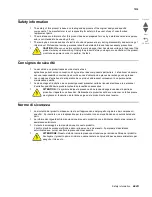
The safety of this product is based on testing and approvals of the original design and specific
components. The manufacturer is not responsible for safety in the event of use of unauthorized
replacement parts.
•
The maintenance information for this product has been prepared for use by a professional service person
and is not intended to be used by others.
•
There may be an increased risk of electric shock and personal injury during disassembly and servicing of
this product. Professional service personnel should understand this and take necessary precautions.
•
CAUTION:
When you see this symbol, there is a danger from hazardous voltage in the area of the
product where you are working. Unplug the product before you begin, or use caution if the product
must receive power in order to perform the task.
Consignes de sécurité
•
La sécurité de ce produit repose sur des tests et des
agréations portant sur sa conception d'origine et sur des composants particuliers. Le fabricant n'assume
aucune responsabilité concernant la sécurité en cas d'utilisation de pièces de rechange non agréées.
•
Les consignes d'entretien et de réparation de ce produit s'adressent uniquement à un personnel de
maintenance qualifié.
•
Le démontage et l'entretien de ce produit pouvant présenter certains risques électriques, le personnel
d'entretien qualifié devra prendre toutes les précautions nécessaires.
•
ATTENTION :
Ce symbole indique la présence d'une tension dangereuse dans la partie du
produit sur laquelle vous travaillez. Débranchez le produit avant de commencer ou faites preuve
de vigilance si l'exécution de la tâche exige que le produit reste sous tension.
Norme di sicurezza
•
La sicurezza del prodotto si basa sui test e sull'approvazione del progetto originale e dei componenti
specifici. Il produttore non è responsabile per la sicurezza in caso di sostituzione non autorizzata delle
parti.
•
Le informazioni riguardanti la manutenzione di questo prodotto sono indirizzate soltanto al personale di
assistenza autorizzato.
•
Durante lo smontaggio e la manutenzione di questo prodotto,
il rischio di subire scosse elettriche e danni alla persona è più elevato. Il personale di assistenza
autorizzato deve, quindi, adottare le precauzioni necessarie.
•
ATTENZIONE:
Questo simbolo indica la presenza di tensione pericolosa nell'area del prodotto.
Scollegare il prodotto prima di iniziare o usare cautela se il prodotto deve essere alimentato per
eseguire l'intervento.
Содержание X945E
Страница 20: ...xx Service Manual 7510 Go Back Previous Next ...
Страница 25: ...Notices and safety information xxv 7510 Go Back Previous Next ...
Страница 26: ...xxvi Service Manual 7510 Go Back Previous Next ...
Страница 32: ...xxxii Service Manual 7510 Go Back Previous Next ...
Страница 88: ...1 56 Service Manual 7510 Go Back Previous Next TTM theory ...
Страница 97: ...General information 1 65 7510 Go Back Previous Next 3TM theory ...
Страница 104: ...1 72 Service Manual 7510 Go Back Previous Next 1TM theory ...
Страница 111: ...General information 1 79 7510 Go Back Previous Next Duplex ...
Страница 416: ...3 36 Service Manual 7510 Go Back Previous Next Exiting Configuration Menu See Exiting Configuration Menu on page 3 50 ...
Страница 432: ...3 52 Service Manual 7510 Go Back Previous Next ...
Страница 465: ...Repair information 4 33 7510 Go Back Previous Next 4 Remove the media out actuator A Front Bosses Lower view A ...
Страница 475: ...Repair information 4 43 7510 Go Back Previous Next E F ...
Страница 483: ...Repair information 4 51 7510 Go Back Previous Next Connectors A ...
Страница 506: ...4 74 Service Manual 7510 Go Back Previous Next 9 Remove the transfer belt lift latch assembly A A ...
Страница 567: ...Repair information 4 135 7510 Go Back Previous Next 7 Remove the scanner PS cooling fan assembly A Connector A ...
Страница 608: ...4 176 Service Manual 7510 Go Back Previous Next 8 Remove the shafts D 9 Remove the tray support rolls B ...
Страница 623: ...Repair information 4 191 7510 Go Back Previous Next ...
Страница 626: ...4 194 Service Manual 7510 Go Back Previous Next 8 Remove the media feed lift motor B A B Connector Rear ...
Страница 643: ...Repair information 4 211 7510 Go Back Previous Next 4 Remove the tray module drive motor A A Connector ...
Страница 653: ...Repair information 4 221 7510 Go Back Previous Next ...
Страница 714: ...4 282 Service Manual 7510 Go Back Previous Next ...
Страница 715: ...Connector locations 5 1 7510 Go Back Previous Next 5 Connector locations Locations ...
Страница 720: ...5 6 Service Manual 7510 Go Back Previous Next Printhead Polygon mirror motor ...
Страница 725: ...Connector locations 5 11 7510 Go Back Previous Next ...
Страница 726: ...5 12 Service Manual 7510 Go Back Previous Next ...
Страница 729: ...Connector locations 5 15 7510 Go Back Previous Next Switch media size Switch TTM media size ...
Страница 730: ...5 16 Service Manual 7510 Go Back Previous Next Media feed unit assembly Sensor tray 4 feed out ...
Страница 743: ...Parts catalog 7 9 7510 Go Back Previous Next Assembly 8 Media feed unit 3 11 13 5 9 2 10 6 4 12 1 8 6 7 14 ...
Страница 765: ...Parts catalog 7 31 7510 Go Back Previous Next Assembly 29 Electrical 1 3 5 9 2 10 6 4 8 1 7 ...
Страница 768: ...7 34 MFP Service Manual 7510 Go Back Previous Next Assembly 31 Electrical 3 8 9 2 3 7 10 1 5 6 4 ...
Страница 770: ...7 36 MFP Service Manual 7510 Go Back Previous Next Assembly 32 Electrical 4 2 1 4 3 5 7 6 8 9 ...
Страница 774: ...7 40 MFP Service Manual 7510 Go Back Previous Next Assembly 35 ADF base 10 1 3 7 5 9 2 6 4 8 Front ...
Страница 776: ...7 42 MFP Service Manual 7510 Go Back Previous Next Assembly 36 ADF feeder 3 13 7 5 2 12 6 4 8 1 11 10 9 ...
Страница 780: ...7 46 MFP Service Manual 7510 Go Back Previous Next Assembly 38 ADF media guide 3 10 5 9 2 6 8 1 4 7 10 11 12 ...
Страница 787: ...Parts catalog 7 53 7510 Go Back Previous Next Assembly 43 CCD lens assembly 3 11 5 8 2 9 6 4 7 1 10 ...
Страница 792: ...7 58 MFP Service Manual 7510 Go Back Previous Next Assembly 46 Scanner optics 3 7 5 2 6 4 1 2 2 2 1 2 2 ...
Страница 797: ...Parts catalog 7 63 7510 Go Back Previous Next Assembly 50 1TM feed unit assembly 4 3 5 4 1 2 ...
Страница 799: ...Parts catalog 7 65 7510 Go Back Previous Next Assembly 51 1TM media feed unit 3 11 13 5 9 2 10 6 4 12 1 8 6 7 14 ...
Страница 802: ...7 68 MFP Service Manual 7510 Go Back Previous Next Assembly 53 1TM drive and electrical ...
Страница 804: ...7 70 MFP Service Manual 7510 Go Back Previous Next Assembly 54 3TM covers 3 5 2 4 1 ...
Страница 806: ...7 72 MFP Service Manual 7510 Go Back Previous Next Assembly 55 3TM feed unit assembly 4 3 5 4 1 2 4 4 ...
Страница 808: ...7 74 MFP Service Manual 7510 Go Back Previous Next Assembly 56 3TM media feed unit 3 11 13 5 9 2 10 6 4 12 1 8 6 7 14 ...
Страница 810: ...7 76 MFP Service Manual 7510 Go Back Previous Next Assembly 57 3TM left door 5 8 6 1 2 3 7 4 8 4 9 9 9 ...
Страница 812: ...7 78 MFP Service Manual 7510 Go Back Previous Next Assembly 58 3TM drive and electrical ...
Страница 815: ...Parts catalog 7 81 7510 Go Back Previous Next Assembly 60 TTM media trays 3 5 4 3 7 2 6 8 1 ...
Страница 817: ...Parts catalog 7 83 7510 Go Back Previous Next Assembly 61 TTM media tray 3 3 7 5 2 6 1 5 9 8 4 4 3 ...
Страница 824: ...7 90 MFP Service Manual 7510 Go Back Previous Next Assembly 67 TTM drive and electrical ...
Страница 828: ...7 94 MFP Service Manual 7510 Go Back Previous Next ...
Страница 836: ...I 8 Service Manual 7510 Go Back Previous Next ...
Страница 844: ...I 16 Service Manual 7510 Go Back Previous Next ...

