


Diagnostic aids
3-19
7510
Go Back
Previous
Next
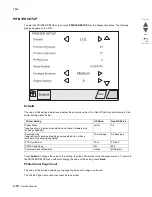
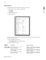
Printed Mono Page Count
The value of this setting enables you to gauge the amount of usage on a device.
The Printed Page Count cannot be reset by the servicer.
Permanent Page Count
The value of this setting indicates the total number of pages that have been printed by the printer.
The Permanent Page Count cannot be reset.
Serial Number
This printer setting records the printer’s serial number that was assigned by the manufacturer. When you select
this setting, a replica of a keyboard appears on the LCD that enables you to edit the serial number.
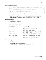
Engine Setting 1 to 4
These settings are used by Engine code ECs to fix field problems.
Warning:
Do not change these settings unless requested to do so by your next level of support.
Model Name
The model name can only be viewed and cannot be changed.
Configuration ID
The two configuration IDs are used to communicate information about certain areas of the printer that cannot be
determined using hardware sensors. The configuration IDs are originally set at the manufacturer, however you
may need to reset Configuration ID 1 or Configuration ID 2 when you replace the printer engine card assembly.
This printer uses two Configuration IDs, each of which consists of eight digits. The first seven digits in each ID
are hexadecimal numbers, while the last digit is a checksum of the preceding seven hexadecimal digits. Each ID
can contain a combination of the digits 0 through 9 and the characters A to F.
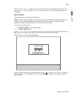
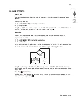
If the printer’s firmware detects that either of the printer’s Configuration IDs has not been defined or is invalid,
then the following occurs:
1.
The firmware automatically uses the Configuration IDs defined for the printer’s standard model.
2.
The Configuration ID setting is the only item that appears when you open the Diagnostics menu.
3.
When the printer is not in Diagnostics mode,
Check Config ID
appears on the LCD.
Note:
Each of the above conditions will remain until a valid value is entered for Configuration ID 1 and
Configuration ID 2.
Содержание X945E
Страница 20: ...xx Service Manual 7510 Go Back Previous Next ...
Страница 25: ...Notices and safety information xxv 7510 Go Back Previous Next ...
Страница 26: ...xxvi Service Manual 7510 Go Back Previous Next ...
Страница 32: ...xxxii Service Manual 7510 Go Back Previous Next ...
Страница 88: ...1 56 Service Manual 7510 Go Back Previous Next TTM theory ...
Страница 97: ...General information 1 65 7510 Go Back Previous Next 3TM theory ...
Страница 104: ...1 72 Service Manual 7510 Go Back Previous Next 1TM theory ...
Страница 111: ...General information 1 79 7510 Go Back Previous Next Duplex ...
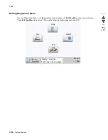
Страница 416: ...3 36 Service Manual 7510 Go Back Previous Next Exiting Configuration Menu See Exiting Configuration Menu on page 3 50 ...
Страница 432: ...3 52 Service Manual 7510 Go Back Previous Next ...
Страница 465: ...Repair information 4 33 7510 Go Back Previous Next 4 Remove the media out actuator A Front Bosses Lower view A ...
Страница 475: ...Repair information 4 43 7510 Go Back Previous Next E F ...
Страница 483: ...Repair information 4 51 7510 Go Back Previous Next Connectors A ...
Страница 506: ...4 74 Service Manual 7510 Go Back Previous Next 9 Remove the transfer belt lift latch assembly A A ...
Страница 567: ...Repair information 4 135 7510 Go Back Previous Next 7 Remove the scanner PS cooling fan assembly A Connector A ...
Страница 608: ...4 176 Service Manual 7510 Go Back Previous Next 8 Remove the shafts D 9 Remove the tray support rolls B ...
Страница 623: ...Repair information 4 191 7510 Go Back Previous Next ...
Страница 626: ...4 194 Service Manual 7510 Go Back Previous Next 8 Remove the media feed lift motor B A B Connector Rear ...
Страница 643: ...Repair information 4 211 7510 Go Back Previous Next 4 Remove the tray module drive motor A A Connector ...
Страница 653: ...Repair information 4 221 7510 Go Back Previous Next ...
Страница 714: ...4 282 Service Manual 7510 Go Back Previous Next ...
Страница 715: ...Connector locations 5 1 7510 Go Back Previous Next 5 Connector locations Locations ...
Страница 720: ...5 6 Service Manual 7510 Go Back Previous Next Printhead Polygon mirror motor ...
Страница 725: ...Connector locations 5 11 7510 Go Back Previous Next ...
Страница 726: ...5 12 Service Manual 7510 Go Back Previous Next ...
Страница 729: ...Connector locations 5 15 7510 Go Back Previous Next Switch media size Switch TTM media size ...
Страница 730: ...5 16 Service Manual 7510 Go Back Previous Next Media feed unit assembly Sensor tray 4 feed out ...
Страница 743: ...Parts catalog 7 9 7510 Go Back Previous Next Assembly 8 Media feed unit 3 11 13 5 9 2 10 6 4 12 1 8 6 7 14 ...
Страница 765: ...Parts catalog 7 31 7510 Go Back Previous Next Assembly 29 Electrical 1 3 5 9 2 10 6 4 8 1 7 ...
Страница 768: ...7 34 MFP Service Manual 7510 Go Back Previous Next Assembly 31 Electrical 3 8 9 2 3 7 10 1 5 6 4 ...
Страница 770: ...7 36 MFP Service Manual 7510 Go Back Previous Next Assembly 32 Electrical 4 2 1 4 3 5 7 6 8 9 ...
Страница 774: ...7 40 MFP Service Manual 7510 Go Back Previous Next Assembly 35 ADF base 10 1 3 7 5 9 2 6 4 8 Front ...
Страница 776: ...7 42 MFP Service Manual 7510 Go Back Previous Next Assembly 36 ADF feeder 3 13 7 5 2 12 6 4 8 1 11 10 9 ...
Страница 780: ...7 46 MFP Service Manual 7510 Go Back Previous Next Assembly 38 ADF media guide 3 10 5 9 2 6 8 1 4 7 10 11 12 ...
Страница 787: ...Parts catalog 7 53 7510 Go Back Previous Next Assembly 43 CCD lens assembly 3 11 5 8 2 9 6 4 7 1 10 ...
Страница 792: ...7 58 MFP Service Manual 7510 Go Back Previous Next Assembly 46 Scanner optics 3 7 5 2 6 4 1 2 2 2 1 2 2 ...
Страница 797: ...Parts catalog 7 63 7510 Go Back Previous Next Assembly 50 1TM feed unit assembly 4 3 5 4 1 2 ...
Страница 799: ...Parts catalog 7 65 7510 Go Back Previous Next Assembly 51 1TM media feed unit 3 11 13 5 9 2 10 6 4 12 1 8 6 7 14 ...
Страница 802: ...7 68 MFP Service Manual 7510 Go Back Previous Next Assembly 53 1TM drive and electrical ...
Страница 804: ...7 70 MFP Service Manual 7510 Go Back Previous Next Assembly 54 3TM covers 3 5 2 4 1 ...
Страница 806: ...7 72 MFP Service Manual 7510 Go Back Previous Next Assembly 55 3TM feed unit assembly 4 3 5 4 1 2 4 4 ...
Страница 808: ...7 74 MFP Service Manual 7510 Go Back Previous Next Assembly 56 3TM media feed unit 3 11 13 5 9 2 10 6 4 12 1 8 6 7 14 ...
Страница 810: ...7 76 MFP Service Manual 7510 Go Back Previous Next Assembly 57 3TM left door 5 8 6 1 2 3 7 4 8 4 9 9 9 ...
Страница 812: ...7 78 MFP Service Manual 7510 Go Back Previous Next Assembly 58 3TM drive and electrical ...
Страница 815: ...Parts catalog 7 81 7510 Go Back Previous Next Assembly 60 TTM media trays 3 5 4 3 7 2 6 8 1 ...
Страница 817: ...Parts catalog 7 83 7510 Go Back Previous Next Assembly 61 TTM media tray 3 3 7 5 2 6 1 5 9 8 4 4 3 ...
Страница 824: ...7 90 MFP Service Manual 7510 Go Back Previous Next Assembly 67 TTM drive and electrical ...
Страница 828: ...7 94 MFP Service Manual 7510 Go Back Previous Next ...
Страница 836: ...I 8 Service Manual 7510 Go Back Previous Next ...
Страница 844: ...I 16 Service Manual 7510 Go Back Previous Next ...


