


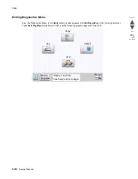


Diagnostic aids
3-41
7510
Go Back
Previous
Next
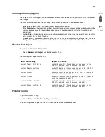
Factory Defaults
Warning:
This operation cannot be undone.
This setting enables you to restore all of the printer’s settings to the base printer settings, the network settings,
or to remove all Lexmark Embedded Solutions (LES) applications.
To restore the Factory Default settings:
1.
Touch
Factory Defaults
from the Configuration Menu.
2.
Touch
Restore Base
to restore all non-critical base printer NVRAM settings.
3.
Touch
Restore Network
to restore all network NVRAM settings.
4.
Touch
Restore LES
to remove all Lexmark Embedded Solution applications.
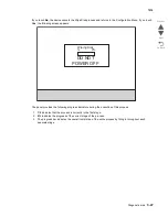
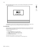
When you select either value, the LCD displays
Restoring Factory Defaults
and then
Resetting the Device
.
The device immediately performs a POR and restores the appropriate settings to their factory default values.
The following settings are not changed:
•
Display Language (general settings)
•
Network/Ports Menu
•
Standard USB, USB (x) Menus (if an ENA is installed)
Energy Conserve
This menu controls what values appear on the Power Saver menu. If
Off
is selected in the Energy Conserve
menu, then
Disabled
appears in the Power Saver menu, and Power Saver can be turned off. If
On
is set in the
Energy Conserve menu, the Power Saver feature cannot be disabled.
To change this setting:
1.
Touch
Energy Conserve
from the Configuration Menu.
[setting's current value]
appears on the
touch-screen.
2.
Touch
or
to scroll through the setting's possible values.
3.
Touch
Back
to cancel and return to the Configuration Menu.
4.
Touch
Submit
to save the change.
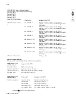
Min Copy Memory
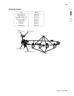
Values will only be displayed if the amount of installed DRAM is at least twice the amount of the value, that is, at
least 200 MB of installed DRAM is required to display the 100 MB selection.
To change this setting:
1.
Touch
Min Copy Memory
from the Configuration Menu.
[setting's current value]
appears on the
touch-screen.
2.
Touch
to decrease the setting's value; touch
to increase the setting's value.
3.
Touch
Back
to cancel and return to the Configuration Menu.
4.
Touch
Submit
to save the change.
Содержание X945E
Страница 20: ...xx Service Manual 7510 Go Back Previous Next ...
Страница 25: ...Notices and safety information xxv 7510 Go Back Previous Next ...
Страница 26: ...xxvi Service Manual 7510 Go Back Previous Next ...
Страница 32: ...xxxii Service Manual 7510 Go Back Previous Next ...
Страница 88: ...1 56 Service Manual 7510 Go Back Previous Next TTM theory ...
Страница 97: ...General information 1 65 7510 Go Back Previous Next 3TM theory ...
Страница 104: ...1 72 Service Manual 7510 Go Back Previous Next 1TM theory ...
Страница 111: ...General information 1 79 7510 Go Back Previous Next Duplex ...
Страница 416: ...3 36 Service Manual 7510 Go Back Previous Next Exiting Configuration Menu See Exiting Configuration Menu on page 3 50 ...
Страница 432: ...3 52 Service Manual 7510 Go Back Previous Next ...
Страница 465: ...Repair information 4 33 7510 Go Back Previous Next 4 Remove the media out actuator A Front Bosses Lower view A ...
Страница 475: ...Repair information 4 43 7510 Go Back Previous Next E F ...
Страница 483: ...Repair information 4 51 7510 Go Back Previous Next Connectors A ...
Страница 506: ...4 74 Service Manual 7510 Go Back Previous Next 9 Remove the transfer belt lift latch assembly A A ...
Страница 567: ...Repair information 4 135 7510 Go Back Previous Next 7 Remove the scanner PS cooling fan assembly A Connector A ...
Страница 608: ...4 176 Service Manual 7510 Go Back Previous Next 8 Remove the shafts D 9 Remove the tray support rolls B ...
Страница 623: ...Repair information 4 191 7510 Go Back Previous Next ...
Страница 626: ...4 194 Service Manual 7510 Go Back Previous Next 8 Remove the media feed lift motor B A B Connector Rear ...
Страница 643: ...Repair information 4 211 7510 Go Back Previous Next 4 Remove the tray module drive motor A A Connector ...
Страница 653: ...Repair information 4 221 7510 Go Back Previous Next ...
Страница 714: ...4 282 Service Manual 7510 Go Back Previous Next ...
Страница 715: ...Connector locations 5 1 7510 Go Back Previous Next 5 Connector locations Locations ...
Страница 720: ...5 6 Service Manual 7510 Go Back Previous Next Printhead Polygon mirror motor ...
Страница 725: ...Connector locations 5 11 7510 Go Back Previous Next ...
Страница 726: ...5 12 Service Manual 7510 Go Back Previous Next ...
Страница 729: ...Connector locations 5 15 7510 Go Back Previous Next Switch media size Switch TTM media size ...
Страница 730: ...5 16 Service Manual 7510 Go Back Previous Next Media feed unit assembly Sensor tray 4 feed out ...
Страница 743: ...Parts catalog 7 9 7510 Go Back Previous Next Assembly 8 Media feed unit 3 11 13 5 9 2 10 6 4 12 1 8 6 7 14 ...
Страница 765: ...Parts catalog 7 31 7510 Go Back Previous Next Assembly 29 Electrical 1 3 5 9 2 10 6 4 8 1 7 ...
Страница 768: ...7 34 MFP Service Manual 7510 Go Back Previous Next Assembly 31 Electrical 3 8 9 2 3 7 10 1 5 6 4 ...
Страница 770: ...7 36 MFP Service Manual 7510 Go Back Previous Next Assembly 32 Electrical 4 2 1 4 3 5 7 6 8 9 ...
Страница 774: ...7 40 MFP Service Manual 7510 Go Back Previous Next Assembly 35 ADF base 10 1 3 7 5 9 2 6 4 8 Front ...
Страница 776: ...7 42 MFP Service Manual 7510 Go Back Previous Next Assembly 36 ADF feeder 3 13 7 5 2 12 6 4 8 1 11 10 9 ...
Страница 780: ...7 46 MFP Service Manual 7510 Go Back Previous Next Assembly 38 ADF media guide 3 10 5 9 2 6 8 1 4 7 10 11 12 ...
Страница 787: ...Parts catalog 7 53 7510 Go Back Previous Next Assembly 43 CCD lens assembly 3 11 5 8 2 9 6 4 7 1 10 ...
Страница 792: ...7 58 MFP Service Manual 7510 Go Back Previous Next Assembly 46 Scanner optics 3 7 5 2 6 4 1 2 2 2 1 2 2 ...
Страница 797: ...Parts catalog 7 63 7510 Go Back Previous Next Assembly 50 1TM feed unit assembly 4 3 5 4 1 2 ...
Страница 799: ...Parts catalog 7 65 7510 Go Back Previous Next Assembly 51 1TM media feed unit 3 11 13 5 9 2 10 6 4 12 1 8 6 7 14 ...
Страница 802: ...7 68 MFP Service Manual 7510 Go Back Previous Next Assembly 53 1TM drive and electrical ...
Страница 804: ...7 70 MFP Service Manual 7510 Go Back Previous Next Assembly 54 3TM covers 3 5 2 4 1 ...
Страница 806: ...7 72 MFP Service Manual 7510 Go Back Previous Next Assembly 55 3TM feed unit assembly 4 3 5 4 1 2 4 4 ...
Страница 808: ...7 74 MFP Service Manual 7510 Go Back Previous Next Assembly 56 3TM media feed unit 3 11 13 5 9 2 10 6 4 12 1 8 6 7 14 ...
Страница 810: ...7 76 MFP Service Manual 7510 Go Back Previous Next Assembly 57 3TM left door 5 8 6 1 2 3 7 4 8 4 9 9 9 ...
Страница 812: ...7 78 MFP Service Manual 7510 Go Back Previous Next Assembly 58 3TM drive and electrical ...
Страница 815: ...Parts catalog 7 81 7510 Go Back Previous Next Assembly 60 TTM media trays 3 5 4 3 7 2 6 8 1 ...
Страница 817: ...Parts catalog 7 83 7510 Go Back Previous Next Assembly 61 TTM media tray 3 3 7 5 2 6 1 5 9 8 4 4 3 ...
Страница 824: ...7 90 MFP Service Manual 7510 Go Back Previous Next Assembly 67 TTM drive and electrical ...
Страница 828: ...7 94 MFP Service Manual 7510 Go Back Previous Next ...
Страница 836: ...I 8 Service Manual 7510 Go Back Previous Next ...
Страница 844: ...I 16 Service Manual 7510 Go Back Previous Next ...


